Hello,
as per the given:
A) loading of one section
Given nominal torque & geometrics etc.: 9550*400*2/(306*0,395*452,4) = 140 N/mm²
B) loadbearing capac. of material (~Eurocode 3 / general)
Given fy with 235 N/mm² & γF to 1,5 & shear: 235/(1,5*sqrt(3)) approx. 90 N/mm²
Concluding:
One section would not suffice to transmit the full load. It is necessary to consider the second pin. The load distribution between these is statically indeterminate, as a rule of thumb (refer parallel keys) we assume an effective influence of 1,5. So:
90*1,5 = 135 N/mm² which is approximately equal to the load. At a give or take something philosophy, one could consider that this is ok.
So it is necessary to go into detail, and here there's not enough database to get a stringent conclusion.
Let's try:
a) Usually, to make up for defects within the material, EC3 & Co lower the loadbearing capac. of material by γM of 1,1
b) you state a possible overloading of 1,1 over the nominal
90*1,5/1,1=123 N/mm² whereas 140*1,1= 154 N/mm².
This is not soundly acceptable.
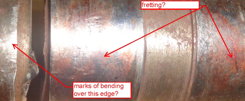
From your picture:
one could conclude that the shear pin was fixed on one side but was able to move on the other side, which would have induced a bending load (however small) onto the section in question.
Prediction (pls. allow me... ;-)
The fracture shall have started at a single point due to some bending effect and shall have developed as a fatigue crack over a longer period, as the base material is quite ductile. The final crack might show a bending to shear overlay of patterns.
remaining questions
- views on the fracture surfaces
- Check of 400 kW @ 306 rpm and/or info about drive setup & configuration
- derivation of Sf 1,5 in your calc: if factor of safety, where did you take it from and why was this value applied?
- Why was HRC test applied to this low fu / high ductility material? EN 18265 even does not give correlation values at HRC for this range of fu. Perhaps HRB testing is to be preferred?
Regards
R.
RSVP