Eng-Tips is the largest forum for Engineering Professionals on the Internet.

Members share and learn making Eng-Tips Forums the best source of engineering information on the Internet!

  • Congratulations JStephen on being selected by the Eng-Tips community for having the most helpful posts in the forums last week. Way to Go!

Factored two-way shear stress in THICK pile cap due to pile - take moment at cap centerline or bottom face?

Ronengo

Structural
Joined
Apr 15, 2025
Messages
6
Hi all, I think I have a relatively simple question that we are getting pushback on.

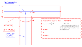
Please see the attached sketch. We have a very thick pile cap and a very large pile.

For the two-way shear stress check, would you take Msc as Mpile (moment at bottom face of pile cap), or would you take Msc as Mlink (moment at centerline of pile cap)?

I think the answer would simply be the centerline if the pile cap was thin. However, given that it's an extremely thick and stiff pile cap, we are getting pushback on whether the moment we consider should actually be at the bottom face of the pile cap.

Any thoughts or references are very welcome. Thanks in advance!
1753469201083.png
 
Given the thickness of the pile cap and the diameter of the pile, what are the other dimensions of the structure? Length of pile, size of pile cap etc.

If the question concerns the local effects I would use a model with volume elements to check the stress distribution.
 
For the two-way shear stress check, would you take Msc as Mpile (moment at bottom face of pile cap), or would you take Msc as Mlink (moment at centerline of pile cap)?
How did you model the pile cap and pile ? Is this a raft foundation supported on piles?
Pls provide more info. ( size of the pile cap , number and spacing of piles ..) to get better responds.
 
@canwesteng Any references you can provide that show this done as an acceptable method? This would be a great help for us but need to justify it to the reviewers.

@ThomasH Piles are long (75 ft) and pile cap is actually the base slab of a large building (180ft x 180ft). Our seismic loads are huge, which is why we are being so particular about where we can take the applied loads from the caisson for the two way shear stress.

The solid elements suggestion is interesting, any references you might be able to share as far as how to use analytical output to obtain the two way shear stress demand?

@HTURKAK Pile cap is plate elements, pile is a member. Connected through the pile cap thickness with a rigid link, as sketched above. Yes it is a large raft foundation on piles, it is a large raft (180 ft x 180 ft) with a lot (80+) of piles
 
For the punching check you are checking for the unbalanced moment within the slab/mat so should be looking at the moment delta between the spans entering and exiting the pile location. In this case that likely matches M,link.
 
@ThomasH Piles are long (75 ft) and pile cap is actually the base slab of a large building (180ft x 180ft). Our seismic loads are huge, which is why we are being so particular about where we can take the applied loads from the caisson for the two way shear stress.

The solid elements suggestion is interesting, any references you might be able to share as far as how to use analytical output to obtain the two way shear stress demand?
I don't have any references but my idea would be to use FEM to get an understanding for the behaviour, stress distribution and things like that. Since the dimensions are larger then the usual connection I would go a bit outside the standard "box".

How to do it in practical terms also depends on the capabilities of the software you use, now I mean the postprocessing. Anything might be possible but some things may require a lot of work. One option might be to do an analysis and simply make a section cut to get the stresses in the connection

Another idea that came from a different thread in the forum, have you considered the strut-and-tia method? I know people that use if for thick foundations and what you have is not entirely different.
 
@HTURKAK Pile cap is plate elements, pile is a member. Connected through the pile cap thickness with a rigid link, as sketched above. Yes it is a large raft foundation on piles, it is a large raft (180 ft x 180 ft) with a lot (80+) of piles
I assume you have modelled the raft with FEM plate elements and the pile with rod, line element. Consider the old method of analysis and modelling the plate with column strips and middle strips where the column strip columns in this case are the piles.. The imaginary beam column strip stiffness would be pretty high when compared with pile stiffness. The moment difference btw the two spans would be pile moment and checking for the centerline moment would be reasonable.
On the other hand , the critical surface would be a cylindrical surface with dia ( 8+10 =18 ft ) regardless of the Mlink or Mpile and the failure surface would be a frustum with bottom face dia 8.
IMO, the model should be improved. Modelling 8 ft dia pile with sinle line element would be overkill for the hogging moments. THe pile locations could be adjusted to match with superstructure column and shear wall locations .
My opinion ..
 
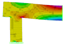
If you have a FEM pacakage you can visually look at your stresses quite easily. This model took about 5min to create. By adjusting the stress levels you can get a very good visual que of how the forces flow to the pile.

1753882306745.png
 
Last edited:
I doubt punching shear controls on a 10' thick mat with an 8' diameter caisson, unless you're at a corner. What are your punching shear results for both options? Are you in a situation where it doesn't work if you consider it at mid-thickness of the mat? If both scenarios work, design for the worst case and move on. Don't make it a research project; you probably don't have it in your budget.
 
@canwesteng Any references you can provide that show this done as an acceptable method? This would be a great help for us but need to justify it to the reviewers.

@ThomasH Piles are long (75 ft) and pile cap is actually the base slab of a large building (180ft x 180ft). Our seismic loads are huge, which is why we are being so particular about where we can take the applied loads from the caisson for the two way shear stress.

The solid elements suggestion is interesting, any references you might be able to share as far as how to use analytical output to obtain the two way shear stress demand?

@HTURKAK Pile cap is plate elements, pile is a member. Connected through the pile cap thickness with a rigid link, as sketched above. Yes it is a large raft foundation on piles, it is a large raft (180 ft x 180 ft) with a lot (80+) of piles
The only reference is the code itself and an understanding of what the one way shear equation represents. The code kicks you out of one way shear equations in D regions, and these equations assume a diagonal shear crack with some frictional force along the crack. In a D region there isn't space for the crack to occur
 

Part and Inventory Search

Sponsor

Back
Top