Continue to Site

Eng-Tips is the largest engineering community on the Internet

Intelligent Work Forums for Engineering Professionals

  • Congratulations cowski on being selected by the Eng-Tips community for having the most helpful posts in the forums last week. Way to Go!

Experience Requested about the instantaneous trip time of a Solid State Relay on a Main SWGR?

Status
Not open for further replies.

bdn2004

Electrical
Jan 27, 2007
799
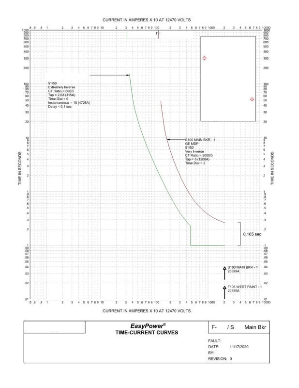
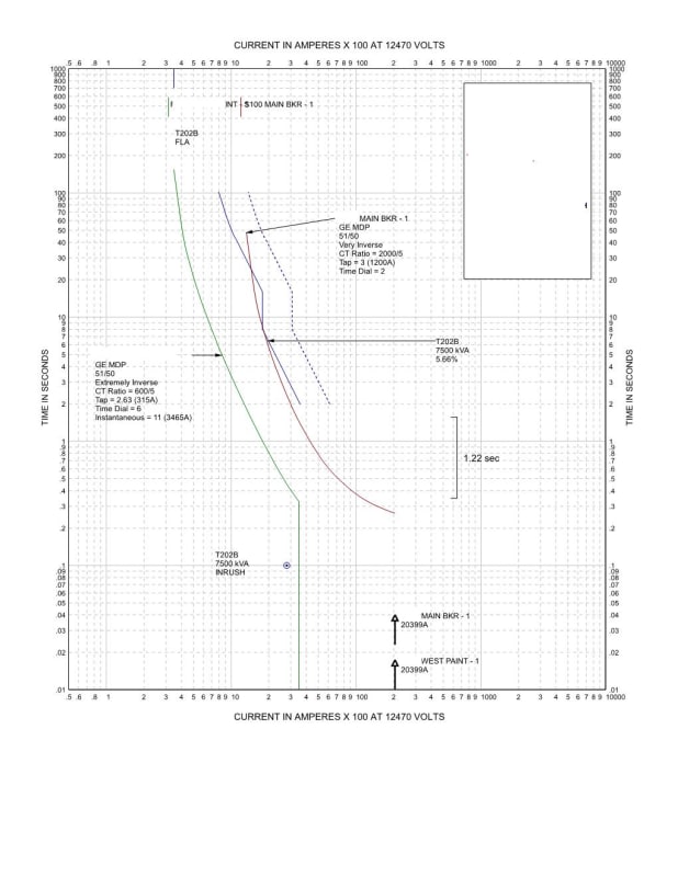
I'm looking at a 12.47kV main switchgear at a Plant site. The EasyPower model have of this indicates there is not enough clearing time between the main breaker on the switchgear and a couple of the feeder breakers.
To put more time between them we could either: decrease the feeder breaker "instantaneous setting" or increase the main switchgear settings. The latter runs the risk of putting the main out of coordination with the Utility.

What is the minimum "instantaneous" setting on solid state relay? Is it different between different relays? I realize nothing is truly "instantaneous" and that's my question.

 
Replies continue below

Recommended for you

It sounds as if the issue is that the main breaker on the 15kV switchgear is not coordinating with the feeder breakers in the instantaneous region. What is the 30 cycle withstand of the main breaker? Did you look at turning off the instantaneous setting for the main breaker? Can the instantaneous trip signal be delayed enough to allow feeder breakers to clear?
 
Decreasing the instantaneous pickup setting on the feeder won't make it any faster if is already tripping on instantaneous. You can assume the instantaneous element will operate within a cycle, probably faster. But you still have the breaker opening time, etc. For digital relays, you need a time separation of roughly 0.2 to 0.25 sec between the relay curves. So you may be able to reduce the instantaneous pickup on the feeder to improve coordination with the main time overcurrent, but this could create coordination issues downstream of the feeder. There will also be arc-flash considerations if you slow down the main breaker relay.

If the utility settings miscoordinate with the main at a slower setting, then maybe the utility relay doesn't coordinate with the feeders either. Probably need more information to offer any concrete suggestions.
It's always a compromise.

 
I don't use an instantaneous on my mains, but I do use a bus differential on the bus for arc-flash. The feeders typically only have time over currents, except we use a maintenance instantaneous for hot line work, with the reclosing removed.
The main typically is a secondary for a failed feeder breaker, but with a typical bus rating of 2000 amps, the main must be set rather high.

About the only times the main would operate is for a two feeder fault, which is rare.
 
TCC-1_plot_iejuky.jpg
 
The instantaneous is off on the main breaker ... the upper curve. The feeder breaker relay has adjustments down to 0. As you can see it set on a delay of 0.1.
I'm saying to get that 0.2 to 0.25 separation would you lower that setting on the feeder breaker ? The fault currents shown are when this is faulted on that feed 10' outside of the switchgear.
And is that 0.2 to 0.25 seconds including the time of the breaker opening? In this case, these are 5-cycle (0.083 seconds) breakers.

Because in the software it says the ss relay to ss relay time only needs to be 0.1 seconds.

I'll find out the the 30-cycle withstand. This is an existing installation. And a very well known large company did the original coordination.
 
0.1 seconds, is about 6 cycles, I typically would want 12 cycles, but that's me.

Other options is rase the main, or use a different curve shape. Maybe something flatter.

Last thing is punt, if all else fails.

 
I am punting. That's already the call for me cause I'm not the Head Coach. I just want to clearly lay out the options and clearly demonstrate the issues of what I've found.

At this particular Plant they had a ground fault a couple of years ago that tripped off the feeder breaker, the main and also the Utility.
At that time they were installing a new unit substation and the high voltage cables were not properly terminated, tracked and shorted.
They resolved that on their own but I'm thinking why did that trip the main too? Isn't that the exact situation you never want to happen?

I've been told that main is only there to provide isolation. And there is bus differential on that bus. I don't really understand why you don't just bump it way up - enough to protect the gear - and that's it.
And never run the risk of tripping both the main and feeders.
 
In my case, I have a transformer that I must also protect above the main. Then again, I am not operating a plant. I am operating a utility.

An issue for me that maybe you don't see is that the faster I can clear feeder faults, the less damage I see, over the years, on the power transformer.
As damage adds up from each through fault, time and duration.

Then again, it is likely you won't see many faults on a plant protection system.
Or maybe you will, in the case if you are a meat packing plant that is cold and wet.

 
I have an old book (1977) "The Switchgear and Control Handbook" that has interesting info. It's before the digital age...
That chart at the top right is calling for 0.4 - 0.5 seconds between relays and none operating in the instantaneous range as per that graph on the left.

It appears to me this is sort of how the coordination in this plant was intended: nothing is started before 0.1 seconds - above the instantaneous range.
I'd like to have a more modern version of this book.

High_voltage_coordination_chart_aflek3.jpg
 
Table 15-2 in the Buff Book 2001 shows the interval time to be 0.2 seconds SS to SS relays. And that does include the 5-cycle breaker opening time.

To answer my own question out of the Switch gear manual as to why perhaps the delay was used on this relay setting:

...."instantaneous devices tend to "overreach" and operate on currents that are apparently lower than the relay setting. Since no time delay is involved, the instantaneous device tends to operate on the the instantaneous asymmetrical current values. The time-delay relays are restrained until the asymmetrical current has dissipated, but the instantaneous relay will operate on this offset current and hence cause the "overreach" problem.


I found another article in that book is helpful. And I think this is what I'm going to suggest.

"Time-Delay Relay over Time-Delay Relay with an Instantaneous Attachment". The time margin at the maximum available fault current can be shortened and the total system operating time reduced by the judicious use of instantaneous elements which cut short the time delay curve so that any current higher than the pickup of the instantaneous unit will cause the unit to operate before the time delay element. This allows the coordination point to be moved back to the current value represented by the instantaneous element pickup. ------> The safety margin between devices can be applied at this point instead at the maximum current value with great advantage because of the inverse nature of the time-delay overcurrent relay. "

Coordination_F105_vrdbai.jpg
 
There is a correct statement in that SS relays with an instantaneous do tend to operate for lower currents then expected.

That has to do with the fact that most fault studies are symmetrical, and most faults are asymmetrical.

The older electromechanical relays would have an unintended delay for currents just over the pickup, which the SS relays do not.
This made up for the operation on the asymmetrical part of a symmetrical fault current that was just below the pickup.

 
Status
Not open for further replies.

Part and Inventory Search

Sponsor