Continue to Site

Eng-Tips is the largest engineering community on the Internet

Intelligent Work Forums for Engineering Professionals

  • Congratulations waross on being selected by the Eng-Tips community for having the most helpful posts in the forums last week. Way to Go!

Evaluating the stability of a single I beam

MIKE_311

Structural
Feb 15, 2020
111
I am working on a design where I have 2 simply supported, single span (30ft), deep steel I beams (80" deep, 24" flanges) that will be used as supports for moving concentrated load (~1000 kip) on the top of each flange. ~3" thick flanges and webs.

The beams are too far apart (50ft) to tie them together with bracing. I was planning to get around the instability issues by setting the beams into concrete, at least half depth, if not more.

I'm looking for guidance on design and detailing requirements to ensure stability, and to ensure the LTB capacity equations used for design are valid. There is room to put some sort of end supports, or knee braces at the ends but I'm not finding a whole lot of guidance on how to design, of what forces to design to. For discrete bracing we usually use 2% of the flange force.

With the concrete, is plain concrete infill adequate? do I need to provide studs to establish composite action?

Any guidance would be appreciated.

Screenshot 2025-05-05 080328.png
 
Last edited:
Replies continue below

Recommended for you

You need to provide a sketch of what you are proposing. Shear studs should be used if you plan to use concrete to provide bracing however yet again this isn’t clear how this is being implemented.
 
You need to provide a sketch of what you are proposing. Shear studs should be used if you plan to use concrete to provide bracing however yet again this isn’t clear how this is being implemented.

I'll add a sketch, but the analysis is basically a single beam on two bearing supports with a moving concentrated load. Simple statics/mechanics 101 problem, but the assumption that the top of beam ends are braced laterally is removed, so L/r would not be valid as K =/= 1 for the top compression flange. The beam would be restrained on the bottom flange at the supports. The beam is adequate for LTB under the loads, assuming the ends are braced.

So, I need some way to ensure stability, but I'm unsure simply insetting the beam into the concrete will provide the necessary stability, or if I need to design/provide end supports, and if so, what lateral loads are they designed for?

I question the shear studs because the concrete wont be bracing the compression flange (like a bridge girder).
 
So in short you want fixed ends? Like an integral abutment? The shear studs them would need to go on an end plate similar to a column base plate, but I would imagine the forces to be quite large at the ends, this might prove challenging.
 
So in short you want fixed ends? Like an integral abutment? The shear studs them would need to go on an end plate similar to a column base plate, but I would imagine the forces to be quite large at the ends, this might prove challenging.

I don't want fixed ends. I want to ensure the top flange is braced at the end and since is going to be sitting on its own, and relatively deep, the entire beam is stable.

The concrete infill is only being proposed for stability.

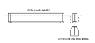
I added a sketch.
 
What kind of structure is this? A crane runway beam? a railway bridge? a highway bridge? There may be different requirements for each type of structure depending on the code that governs.
 
Can you not just size it completely with a completely unbraced top flange? If you have a 24" top flange I bet the unbraced length before LTB starts actually lowering your moment capacity.
 
Can you not just size it completely with a completely unbraced top flange? If you have a 24" top flange I bet the unbraced length before LTB starts actually lowering your moment capacity.
I agree. At a 30' length with 24"x 3" top flange, you shouldn't have any reduction in capacity for LTB, as long as the ends are braced.
 
I agree. At a 30' length with 24"x 3" top flange, you shouldn't have any reduction in capacity for LTB, as long as the ends are braced.
The top flange at the ends are not braced only the bottom flange.

@MIKE_311 Can you not touch the top flange at the ends at all? How far down from the top flange before you can brace? You are showing web stiffeners, can you add diagonal braces going down, near the top flange?
 
I agree. At a 30' length with 24"x 3" top flange, you shouldn't have any reduction in capacity for LTB, as long as the ends are braced.
I just did a quick check on the beams strength, and the moment capacity of this size of beam is INSANELY high. Even fully unsupported on the top, before LTB actually starts reducing section strength you need to be 35m+ in length.

@MIKE_311 did you list the dimensions correctly in your question? This beam seems commically large.

Your question says 1000kips on the top of each flange. Do you mean to say that there are a pair of 1000kip loads? Even so, if you stick both of these at midspan you get a moment of roughly 20400kN-m and the beam is good for like 49000kN-m.

And with webs 3" thick you might not have to worry about web cripping/yielding either.
 
I was planning to get around the instability issues by setting the beams into concrete, at least half depth, if not more.

Yes, that should definitely work for LTB. In spades.

With the concrete, is plain concrete infill adequate?

I'm sure that it is adequate. Obviously, the concrete needs to not fall apart under any of the other loads imposed upon it but that shouldn't be a big deal.

Make sure that the concrete restrains the beam on both sides. An "edge" condition where the rollover of the beam would tend to separate it from the concrete would require some additional attention.

do I need to provide studs to establish composite action?

No, you don't.

and if so, what lateral loads are they designed for?

It sounds as though the concrete would be providing roll over style LTB bracing to the girder. There's an appendix in the AISC steel construction manual. I'd have to think that something bridge specific also exists someplace however.
 
What kind of structure is this? A crane runway beam? a railway bridge? a highway bridge? There may be different requirements for each type of structure depending on the code that governs.
Is there not some lateral load from what you are supporting you need to apply besides just looking at LTB stability?
 

Part and Inventory Search

Sponsor