Continue to Site

Eng-Tips is the largest engineering community on the Internet

Intelligent Work Forums for Engineering Professionals

  • Congratulations KootK on being selected by the Eng-Tips community for having the most helpful posts in the forums last week. Way to Go!

Eurocode 3 - Combined bending and compression, lateral buckling reduction factor not applied to Mz 1

Trusslover

Structural
May 9, 2025
3
Hello dear colleagues,

After many years browsing this great forum to find useful answers, I have finally created an account to ask my first question which I've had for a while but couldn't find answers to.
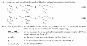
In the Eurocode 3 for steel, when looking at combined bending and compression in section 6.3.3 you find two formulas (see attached) where you combine the utilization ratios of N + My + Mz.

Why do we only apply the Chi LT reduction factor for lateral buckling to My but not Mz?
I often work with square hollow section beams, and I can think of cases where Mz would be greater than My in the structures I work with.
So I usually apply Chi LT to both (which might be conservative?), but I'd like to understand why the codes say otherwise.
 

Attachments

  • Screenshot 2025-05-09 014825.png
    Screenshot 2025-05-09 014825.png
    251 KB · Views: 19
Solution
Why do we only apply the Chi LT reduction factor for lateral buckling to My but not Mz?

I, too, am a lover of trusses. So sexy...

I feel that it is best to try to understand something like this from the perspective of the fundamentals. This will be just one of several valid ways to tell the same story.

1) When a member loaded to produce strong axis moment rolls over onto its weak axis (LTB), its moment of inertia (stiffness) in the direction of the load effectively decreases. Because stiffness decreases, the member deflects more and the load moves closer to the ground. In this way, the potential energy of the applied loads is reduced (like a ball rolling down a hill). Viewed from this perspective, the lowering of...
Replies continue below

Recommended for you

Why do we only apply the Chi LT reduction factor for lateral buckling to My but not Mz?

I, too, am a lover of trusses. So sexy...

I feel that it is best to try to understand something like this from the perspective of the fundamentals. This will be just one of several valid ways to tell the same story.

1) When a member loaded to produce strong axis moment rolls over onto its weak axis (LTB), its moment of inertia (stiffness) in the direction of the load effectively decreases. Because stiffness decreases, the member deflects more and the load moves closer to the ground. In this way, the potential energy of the applied loads is reduced (like a ball rolling down a hill). Viewed from this perspective, the lowering of potential energy is the impetus for LTB.

2) Were a member loaded about it's weak axis to roll over onto its strong axis, its moment of inertia (stiffness) in the direction of the load would effectively increase. Because stiffness increases, the member deflects less and the load moves further from a the ground. In this way, the potential energy of the applied loads is increased (like a ball rolling uphill of its own accord). Obviously, this is not going to happen. Consequently, the LT factor need not be applied to weak axis moment because weak axis lateral torsional buckling is functionally impossible.

How'd I do?
 
Solution
Thank you so much KootK,

I really like your explanation, this now makes sense to me when I think about I beams or rectangular hollow sections.
I was going to ask about square and circular hollow sections but I just remembered that Eurocode 3 says that those sections are not susceptible to lateral-torsional buckling.
Is it because if those sections were to start rolling over, the moment of inertia wouldn't change therefore there wouldn't be any impetus for LTB?
 
Last edited:
Is it because if those sections were to start rolling over, the moment of inertia wouldn't change therefore there wouldn't be any impetus for LTB?

Just so. Rolling an Ix=Iy section usually requires that some energy also be stored as torsional strain. In that sense, it's slightly better than purely neutral stability. Like pushing a ball up a slight incline.
 
I often work with square hollow section beams, and I can think of cases where Mz would be greater than My in the structures I work with.

By definition Y-Y is the strong axis ( for WF , I beams ..) and for square hollow sections they are the same.

1746895137651.png


So I usually apply Chi LT to both (which might be conservative?), but I'd like to understand why the codes say otherwise.
Definition of χLT is ; the reduction factor due to lateral torsional buckling discussed at clauses 6.3.2. ( and χLT = 1.0 for members sufficiently supported laterally and that are not susceptible to torsional deformation such as circular or square hollow sections. Y-Y axis is susceptible to torsional deformation so the reduction factor is applied only strong axis bending resistance My,Rk . In your case χLT = 1.0 for SHS )

I have attached a doc. and there is a worked example to get insight for uniform members in biaxial bending and compression check as per EC-3.
 

Attachments

  • 05_Eurocodes_Steel_Workshop_SIMOES worked examples for freshers.pdf
    5.9 MB · Views: 4
Last edited:
Thank you both,

@KootK ,
Makes sense. Do you think that also applies to square box trusses?
That's a kind of section I often work with, and when I can't model the whole truss in 3D I calculate the moment of inertia of the truss based on the 4 chords, and in that case Ix=Iy.
I seem to remember this procedure from the British standard BS5950 where you could do the flexural buckling calcs of a box truss that way, treating it as one compound member. And then nothing about lateral torsion buckling for such members but given what you explained I would understand if square box trusses were not susceptible to LTB.

I sometimes did some capacity calcs for box trusses in bending where I would only look at the two chords in compression, calculate the maximum moment of inertia of those two chords together but spaced out as they are, and that would give me the flexural buckling capacity of that half box truss. That multiplied by the depth of the whole box truss would give me what I hoped would be the LTB capacity of the box truss.
I only used that as an indication, and if the answer to my first question is yes then I guess that would be useless for square box trusses. But maybe not for rectangular box trusses?

Sorry, I can be quite nerdy when it comes to trusses, hence the name.


@HTURKAK ,
Thank you for the document, I remember finding a similar version online a while ago but all the scientific characters in formulas had been turned into weird text as though converted somehow, thus difficult to use. I'll try again with your version.
And I agree regarding the definitions. When I get biaxial bending in a square hollow section, I just don't think in terms of strong/weak axis, but vertical z and lateral y. That's what I meant by sometimes getting Mz>My.
 
Do you think that also applies to square box trusses?

I do, in general. Some additional considerations:

1) The shear flexibility of the cross section as represented by the webbing.

2) Loads that are other than straight through the shear center of the truss.

But maybe not for rectangular box trusses?

Similar to HSS, you have to get pretty un-boxy before LTB usually becomes an issue. Beyond an aspect ratio of 1.5 to 2.0 additional consideration of some kind is probably warranted. At first blush, you method sounds decent so long as you've got something in there for the lateral shear flexibility of the webs.
 

Part and Inventory Search

Sponsor