surya teja
Structural
Hi everyone,
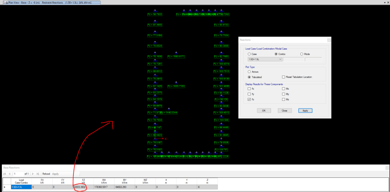
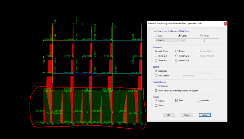
I am trying to model a building where I have a wall that runs in the first two storeys and then only columns continue from the second storey to roof. I have modelled my wall as a shell element in first two storeys and column as line element from second storey to roof. Also I made sure that at the point of connection of the column to the wall, the wall has been meshed manually. Now the issue I am facing is that when I see the axial load diagrams for vertical load, I see that just from the wall-column junction the axial load value actually starts reducing. I tried to check in the analysis base reactions of etabs which gives me almost expected value by a similar model where there is no wall and only columns have been modelled. However, when I try to add manually from the each of joint reactions of vertical reactions at the base, the total value seems a lot less.
Your inputs are really appreciated.