Continue to Site

Eng-Tips is the largest engineering community on the Internet

Intelligent Work Forums for Engineering Professionals

  • Congratulations waross on being selected by the Eng-Tips community for having the most helpful posts in the forums last week. Way to Go!

EPANET System Unbalanced

Status
Not open for further replies.

SabrinaPAE

Civil/Environmental
Sep 7, 2017
8
Hi all,

I'm new to this forum, but am struggling with an error message I am receiving in EPANET.

I am modeling the existing water system for a University in West Michigan. I am using a tank as the supply to the system, and adding nodes to respective locations to add demand to buildings in the University.

There are two double check valves/back flow preventers at the beginning of the system that I am modeling as a GPV with a head loss curve. There are three hydrant flow tests I am using to calibrate my system. When I place no demand on any hydrant and run the model, I get an error message saying that the system is unbalanced at 0+00 hours. However, when I place demand on any one hydrant, the model runs fine...

I can not figure out why this is happening for the life of me, and would really appreciate some input. I've attached the .net file for the system I am modeling.

If anyone has any tips, I would be extremely grateful!

Thanks!

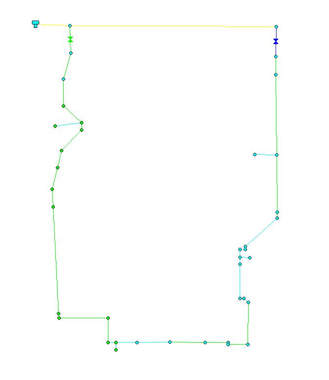
See below for a .jpeg snapshot of the system:
System_jmdijl.jpg
 
Replies continue below

Recommended for you

I have not downloaded your .net but my first question is, do you have demand with both hydrants off?
or is this just a fire system model?
if so put a tiny demand on one of the far nodes from the sources
otherwise the system is trying to divide by zero

Hydrae
 
I have demand with all three hydrants off, yes. I am using demand at hydrants to calibrate the model, from hydrant flow tests. I already have demand on various nodes in the system corresponding to REU tables based on building type - are you suggesting to put a small demand at one of the hydrants?

If you open up the file, you will see that the model will run with CU4 @ valve 2, but I get an error message if I try using CU5 @ valve 2. I want to use CU5, because I believe that models the headloss across valve 2 more accurately (we have data that shows a 10 psi drop across valve 2). Additionally, there is hydrant that was flowed at 1000 gpm just SW of valve 2 near the Athletic Center and was gauged just south of valve 2 - when placing a 1000 gpm demand on this hydrant, I should be seeing a 20 psi residual at the gauge location...

I've updated the model a bit and have attached it below.
 
 http://files.engineering.com/getfile.aspx?folder=7bab724b-cb63-4004-9317-3ea1add35cb4&file=Existing_Conditions_w_Pump_Curve.net
The GPV valves have nonlinear curves, in areas where the curves are inverted it cannot decide how much flow to put through each valve. It ends up in a chattering situation, add more flow on one leg of the loop the pressure goes up not down so more flow can go, then the flow exceeds the demand so it starts over.

This can actually happen in real life but is rare, momentum is not part of EPAnet Calculation engine, so EPAnet can not accurately model this system. But if the system did chatter at these low flows I suspect the operator would notice the chatter stops if the loop is closed and nobody is the wiser.

Hydrae
 
So what is the solution to this? Should I not use the GPV curves I generated? I obtained them from manufacturer specs, but am open to doing the "right" model.

Update: I ended up simplifying the curves I created to make them linear, system is never unbalanced now.

Last question (see attached image for reference) - I have a hydrant flow test where 820 gpm was flowed at the SW hydrant, and the hydrant gauged toward the NW showed a static and residual pressure of 44 and 28 psi, respectively. However, when I place the 820gpm demand on the SW hydrant, I only see a 4 psi drop (goes from 44 psi to 40 psi) at the hydrant gauged, i.e. when I placed demand on the hydrant flowed, I am seeing a residual pressure of 40 psi, when I should be seeing a residual of 20 psi. Any idea why this is happening?

 
Modeling and/or operating systems that do not have a single positive control mechanism can result in undefined operating parameters, the classic example is a loop fed by 2 pressure reducing valves, it is difficult to get both PRV's to flow under low flow conditions especially when the PRV's are pilot controlled, Higher flows are fine since the friction losses allow both sources to be engaged, your example is compounded by the non linear curves.

In your case, you may be able to make one of the sources non linear for a better model
one of the methods I like to do on things like that, is to engage time function and have demands change over time

On your follow up question
The gauged hydrant does not show the losses between the 2 hydrants so the measured residual is
higher, best to gauge a port just downstream of the hydrant flowed, but locations where that is possible are rare.

Hydrae
 
Please see the attached and updated model - I created a curve (CU6) and applied that curve to both GPV's. The curve does not have any inverted curves, as you previously mentioned, and I've modeled the pressure drop across the double check valve & backflow preventer accurately (there should be a 10psi drop across the valve).

Is my model "correct"? From what you said above, it seems like I created a model that is resulting in undefined parameters and should be changed, but I am seeing fairly accurate calibration between the flow tests...
 
 http://files.engineering.com/getfile.aspx?folder=5567e9da-504e-4767-8fda-91bd9764dfc0&file=Existing_Conditions.net
There comes a time in every project when you shoot the engineer and go into production

Hydae
 
I don't quite understand what you're saying.
 
Sabrina,

Have you considered the headlosses that will occur in the distribution system upstream of where your connections are. Your model shows an elevated tank with a hydraulic grade of 932 ft situated about 150 ft from your western most connection. Is there actually an elevated tank located at that location? Was this the actual hydraulic gradeline at the storage tank when the hydrant flow test was performed? Is your system connected to a 16-inch main as your model shows?If the storage tank isn't located as close to your western most connection as your model indicates and your system isn't connected to a 16-inch main, you are not accurately modeling the headlosses in the distribution system when it delivers the flow to your system.

I suspect that is the issue you are seeing with the minimal headloss when modeling the fire flow. When I have analyzed a system like this in the past, I have used a pump connected to a reservoir as the source. The pump curve is then modeled to represent the headlosses in the upstream distribution system.

Hope this helps.
 
Coloeng,

Thank you for your response.

There is not actually an elevated storage tank at that location. I am not sure what the hydraulic gradeline was when the hydrant flow test was performed. I have another hydrant flow test that was conducted on the 16-inch main located near where I have the elevated storage tank, and that flow test shows a static of 45 psi, and a residual of 42 psi. I used the static psi as the initial level of the tank...

The storage tank definitely is not located as close to the western most connection as my model indicates. I only put it there, since that is where a hydrant flow test on the 16-inch main was conducted. I do not have information on the elevated storage tank.

Should I use the pump curve, then? What value would I use for the total head property for the reservoir?
 
Sabrina,

I would probably use the residual as the initial level of the tank if you are concerned with the fire flows.

Your system may not be calibrated. With that much of a difference between field conditions and model results, it would be my guess that there is a valve somewhere in your system that is partially or most of the way closed. This is forcing the majority of the flow through one leg of your system and increasing the headloss. When I close a pipe on the west leg of your system and run the model it gives me negative pressure at J7, which would be consistent with a valve being partially closed on that leg for your field conditions.

Without knowing more about your system, that would be my guess although there could be other causes.
 
Coloeng,

I ended up using a reservoir with a pump curve, with the reservoir set at the surface elevation at that location (see the updated model, attached).

The system is calibrated on the right side of the model given two other hydrant flow tests, but it is the hydrant flow test previously mentioned (on the western/left side of the model) that is giving me calibration issues.

Fortunately, the section of pipe that we are adding a hydrant to is on the East side (right side of the model. Another question - there is a hydrant on the right side of the model (J2) that was gauged and should be showing a static pressure of 41 psi and a residual of 32 psi. I, however, am seeing a static of 33 psi and a residual of 25 psi...the hydrant being flowed is J3 at 862gpm. The pressure entering the right side of the system at the 16-inch main connection should be 45 psi static, but it is about 40 psi. Any ideas or suggestions?

Thank you for all your help! I appreciate you and the fact that we are on the same page. Your explanations are extremely informative and helpful.
 
 http://files.engineering.com/getfile.aspx?folder=9f3847e0-9d65-459f-bdaf-f6c02adab953&file=Existing_Conditions_w_Pump_Curve.net
Sabrina,

If you haven't done so already, check all of your pipes and ensure that the diameter and roughness coefficient are correct, verify that you have assigned the proper demand at each node. Check your GPVs and make sure the headloss curve that you are using is correct. Once you have done that, run the model and check to make sure the total head at your two inlet points looks reasonable for what you expect, then check the pipes and see if you have any that are showing higher headloss than you think is reasonable.

You should be able to identify why your model isn't providing the results you expect.

You're welcome and best of luck.
 
Coloeng,

Which western pipe did you close and see negative pressures at J7? I am trying to replicate that result, and am not able to do so...
 
Status
Not open for further replies.

Part and Inventory Search

Sponsor