Hi,
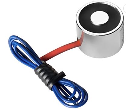
I'm too new to magnetic things but I need to make an electromagnet to measure efficiency of my gearbox (electromagnetic brakes). I've done the calculations so far but there is a question on my mind.
So, I use 1018 mild steel for core material (best available option for me)
24 awg(0.51mm) copper wire for coil
1600 turns
0.5 Amp (max)
0.025m core length
In that case H is about 32000 [A-T/m] and the permeability for the 1018 is about 36.5 [H/m] and the magnetic flux density is 1.46 T. (I've got the values from a graph)
1- If I use 36 mm of magnetization surface( there is no any hole on the surface, full section, area of the surface is 0,00101 m2), the pulling force is about 88kg to my calculations.
2- If I use a hollow surface with the same out diameter, mean if there is a hole of 12 mm across the magnet length on the center (di=12mm, do=36mm, area of this one is 0,000904 m2), pulling force is 78 kg.
Obviously the area decreased, so was the force.
What I'm curious is that, because I drilled a hole in the magnet will there any increase at the flux density? And if will, might the core saturate earlier from 1.6 Tesla? (saturation point is about 1.6 T for 1018)
I heard the saturation point does not depend on the surface area from somewhere, but for example, two materials with the same outer diameter of 50 mm, one with a full cross-section and the other with an empty cross-section, (the empty one is like the same ring, for example with a wall thickness of 2 mm) when the same H is applied to these magnets, will the same amount of magnetic flux be induced in both? or will it have more magnetic flux induced because there is less material in the ring? I'm missing something and this really bothers me.
Thank you.
EDIT**
So, I just went deeper and saw that the magnetic circiut law and that says MMF= flux * Reluctance (flux= B* Area, Reluctance=Length/(mu*area))
MMF=B*Area*L/(mu*Area) Appearently, mmf doesnt depend on area. And if we think physically, mean with the consant mmf, when we remove A of area from the magnetization part, normally the magnetic flux density should increse but at the same time the reluctance of the core material increases at the same ratio and so in the end, B is always constant.
I will be glad if someone confirm me.


