Continue to Site

Eng-Tips is the largest engineering community on the Internet

Intelligent Work Forums for Engineering Professionals

  • Congratulations waross on being selected by the Eng-Tips community for having the most helpful posts in the forums last week. Way to Go!

Elastomeric Expansion Bearings

Status
Not open for further replies.

Guest090822

Structural
Jan 18, 2017
260
The attached photo is for an expansion bearing on a pedestrian truss bridge. The masonry plate and elastomeric portion came as a unit, were installed over the anchor bolts. The truss was then set down and the plate on top of the bearings is welded to the end post of the truss. Both plates have slotted holes. I’ve never seen a masonry plate not bolted firmly to a pedestal. I checked the drawings and this is how it was designed with the exception that the top will be double-nutted (bridge is under construction). The plans say to leave the top nut loose enough to allow movement in the slotted holes. This doesn’t seem right to me, but I also have limited experience with pedestrian bridges. Am I the only one that believes this is a poor design?

6B95545D-91F1-4538-AA04-1414AC25A856_fefo6k.jpg
 
Replies continue below

Recommended for you

Bearings for ped bridges are no different than a non-ped bridge. I've never used this type but I have seen something similar. I have to look through my files tomorrow.
 
Holes in the masonry plate are slotted too? That's weird.

If the bridge configuration is such that there would always be a reasonable gravity reaction at the bearing, and that that gravity reaction is enough to generate friction between the masonry plate and foundation... I don't know that I can identify any issue with the masonry plate being loose.

But I don't understand it either.

----
just call me Lo.
 
Does this bridge have this same detail at both ends of the span?

In the mid-1970's I visited a highway bridge under construction, over tidal water, on the Outer Banks of North Carolina. Both ends of the bridge spans sat on elastomeric bearings, the elastomeric bearing sat on steel bearing plates anchored in the caps. There were no anchor bolts. The intent of the design was to allow rapid span replacement if a span was damaged by water traffic. A barge positioned under the damaged span would be lifted by tide, lifting the span, allowing it to be floated out. Likewise, a replacement span could be floated in and positioned using falling tide.

This installation looks almost identical, except anchor bolts are added and the bearing plate is "loose", but can't go anywhere since it slips over the anchor bolts.

I'll speculate that the bridge is designed to just "sit" on the elastomeric pads. The anchor bolts are not needed except to limit unusual excessive horizontal movement, perhaps cause by a seismic event.

[idea]
 
My guess would be that the slots in the masonry plate are to allow for the bearing to be aligned correctly with the sole plate, even if the superstructure is longer or shorter due to the temperature at the time of setting. With the bearing vulcanized to the masonry plate, once the superstructure is set, under normal operation the slots won't matter.

The slots may serve a secondary purpose in the case of a large seismic event, when the masonry plate may slide, which produces a damping effect, dissipating some of the energy, and limiting the force transferred to the substructure. Thus, it may well be a designed part of the earthquake resisting system (ERS).

Unless you relish the idea of bent or broken anchor bolts, make sure they do back those nuts off of the sole plate, so the superstructure is free to expand and contract. Trust me, the superstructure will expand and contract, even if it's rigidly attached to the abutment. Something will give, and it won't be the superstructure - it'll be the anchor bolts or abutment itself.

Rod Smith, P.E., The artist formerly known as HotRod10
 
BridgeSmith - the slots in the masonry plate are definitely for setting the bearings in the right spot. It just seems to me that without nuts on the masonry plate that the whole bearing may slide on the pedestal, which is just unheard of to me. I share the same concerns for the bolt breaking off. At the top, the bolts are to be left loose so that expansion/contraction takes place at the top of the bearing. I had initially thought they just forgot to put the nuts on at the masonry plate, but the plans didn't call for anything so I'm puzzled. I absolutely know that the superstructure will move no matter what, but just wanted confirmation that I wasn't out in left field thinking this was a weird design. This is a 150 feet long bridge so in the Northeast we are talking a movement in contraction of 1.07 inches (68 degrees to -30 degrees in this area = 98 degrees of one-way movement).
 
It's unlikely that the masonry plate will move under normal conditions. The shear deformation force in the bearing pad would have to be higher than the friction between the masonry plate and the concrete. With a pad that tall, an inch or so of movement wouldn't develop significant lateral force. Additionally, if the masonry plate did move, what would it do to compromise the integrity of the bearing system? I don't see where it would.

The only weird (ok, unusual) part of this is that the pad is vulcanized to the masonry plate, and that it actually has a masonry plate. It was probably necessary for stability because of the high height to length ratio; the height for an unbonded pad is limited to 1/3 of the least plan dimension. Our elastomeric bearings are not bonded. Ours are typically kept in place by keeper bars front and back and the anchor bolts on the sides. They sit directly on the concrete seat. If we have to replace them, we jack would the superstructure a little, slip the old ones out and the new ones in, and move on. To my knowledge, we haven't had to do that on any bridges yet.

Rod Smith, P.E., The artist formerly known as HotRod10
 
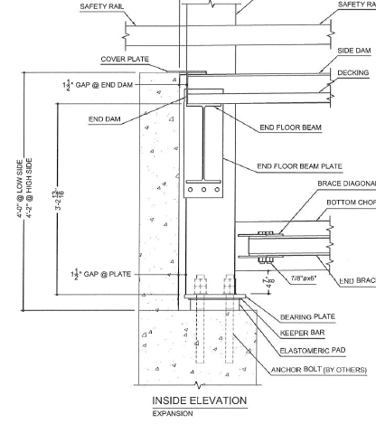
"Ours are typically kept in place by keeper bars front and back and the anchor bolts on the sides" - We have that detail as well on one of the bridges. There are 5 pedestrian bridges and of course two fabricators so they are doing things different. This detail made sense to me. The picture from my first post did not.

Capture_v9fa10.png
 
The dimensions of the bearing pads are often dictated by how much force is allowed to be transmitted to the substructure, and sometimes geometric constraints, as well. The bearing shown in the picture will be very flexible and produce far less lateral force on the abutment when the superstructure expands and contracts, compared to the one in the detail. However, the tall, narrow pad would not be stable against overturning without being attached to a sole plate or masonry plate.

Honestly, I don't see any issues with the bearing configuration shown in the picture. It's somewhat different than what we normally see and normally detail, but I don't see any reason it wouldn't function adequately if it was designed properly.

Rod Smith, P.E., The artist formerly known as HotRod10
 
Attached are bearings from KDOT & ConnDOT. Neither has a masonry plate. The KDOT bearing runs the anchor bolt through a slotted hole in the sole plate. ConnDOT doesn't use anchor bolts; at least on that bridge they didn't. On other projects I've seen them use bearings similar to KDOT. In NY we use masonry and sole plates. The masonry plates for the expansion bearings have slotted holes for installation adjustment. The bridge movement is taken up in the elastomer.

I recall working on an OhioDOT project in the 80's and they didn't bother with anchor bolts; first time I saw that.
 
 https://files.engineering.com/getfile.aspx?folder=9c59fd3d-25e2-42b1-ba69-a601f5ae7cb4&file=Bearing_details.pdf
There is (or at least was) a lateral restraint check in AASHTO for elastomeric bearings to see if they needed a positive connection to the beam seat, typically based on friction as noted by BridgeSmith. As shown, the bearing can't go anywhere unless the vulcanization to the masonry plate fails.
 
There is (or at least was) a lateral restraint check in AASHTO for elastomeric bearings...

There's a check for slip of the bearing pad on the seat or sole plate, which has a couple of uses, one of which is to check for adequate seat width. The other use is to limit the lateral force required for design of the substructures.

Rod Smith, P.E., The artist formerly known as HotRod10
 
Is it common to place an elastomeric bearing on top of a steel plate (aka masonry plate?) like that?

Every elastomeric bearing I have designed placed the pad directly on the concrete with a steel plate on top of the pad. The steel plate is welded to the bottom flange (if a steel girder) or an embedded sole plate (if a PC beam). The anchor rods (not bolts) go through the steel plate and are cast with the concrete.

The bearing shown in that picture seems much more prone to slipping and corrosion by placing that steel plate directly on the concrete, but I suppose it depends on depends on the vertical load on the bearing and if an expansion joint is directly above.
 

Depends on who's boss [lol]

In NY we use sole and masonry plates. Around 10 years ago I came across the KDOT bearing without a masonry plate. Recently, ConnDOT has gone this route also. Also saw a bridge in NJ without the masonry plate. I think the concern has to do with the bearing walking away under heavy lateral load; hence the bottom plate.
 
Well if I was the boss...

I don't think Oklahoma has ever used a masonry plate.

I've seen several curved skewed steel bridges "walk" on their old steel bearings and I've seen old steel roller bearings roll out.

I've never heard of an elastomeric pad slipping out or getting shoved over, but I suppose there is a first time for everything. If it's a concern the pad can be bonded (vulcanized) to the anchor plate above.
 
In Wyoming, we don't use vulcanized (bonded) bearings (with the exception of a couple of bridges with lead-rubber seismic isolators, which obviously have to be bonded top and bottom), and rarely use masonry plates, usually for retrofits replacing rocker bearings. On the sides of the bearings where there aren't anchor bolts to keep the bearings from walking, we put keeper bars (3/4" high) on the sole plates. We haven't had any of those walk out yet.

Rod Smith, P.E., The artist formerly known as HotRod10
 
I've seen highly skewed bridges - skew angle ~30 degrees or more with steel bearings or elastomeric - walk laterally. Elastomeric is not a good choice for these bridges. The elastomer, even if it's vulcanized to the masonry plate, can tear off. It's not the end of the world but water and debris can get underneath and lead to premature failure. In a highly skewed situation multi-rotational bearings are a better choice; omit guide bars on expansion bearings near the facias. This way the bridge can return to its proper alignment.
 
Status
Not open for further replies.

Part and Inventory Search

Sponsor