I did some related work on this in a
past thread which maybe of interest here. Everything that follows is a regurgitation of that work.
-----------------------------------------------------------------------------------------------------------------------------------------
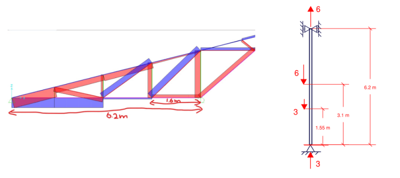
I prepared the attached PDF to answer some questions that I've been interested in since Celt83 conducted a similar exercise. And I thought that they might be of interest to the group. Basically, I wanted to study the flanges of our W27x84 test beam as isolated compression members to get a sense for how the behavior and capacity of such members would be affected by a compression distribution that varies over the length of the member and is substantially tension over segments of the member.
My observations:
1) In many important respects, a beam cannot be considered to be merely an assembly of independent axially loaded fanged. No surprise there. This representation completely ignores that fact that both flanges are continuously braced, to a degree, by the St.Venant torsional stiffness of the beam. That makes a big difference and must be remembered.
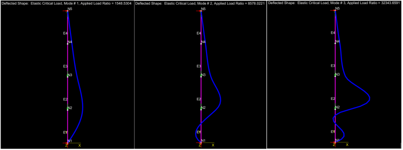
2) Relative to a classic, Euler column, a column loaded like a beam bottom flange would have about double the capacity.
3) A column loaded like a beam bottom flange still buckles over its entire length, as our LTB models have suggested.
4) Relative to a classic, Euler column, a column loaded like a beam top flange would have about fifteen times the capacity. Clearly, a flange with its compression field located at its ends (bottom flange) is much more unstable than a flange with it's compression field located at its middle (top flange).
5) I've come to view LTB, at least for our test case, as something like:
a) the bottom flange initiates some twist.
b) with some twist in play, some of the applied load becomes a weak axis load on the beam and initiates some sway.
Obviously, these are two actions occurring in tandem rather than sequentially.

![[2thumbsup]](/data/assets/smilies/2thumbsup.gif "[2thumbsup] [2thumbsup]")