Continue to Site

Eng-Tips is the largest engineering community on the Internet

Intelligent Work Forums for Engineering Professionals

  • Congratulations waross on being selected by the Eng-Tips community for having the most helpful posts in the forums last week. Way to Go!

eccentrically loaded single foundation 3

Status
Not open for further replies.

mats12

Geotechnical
Dec 17, 2016
181
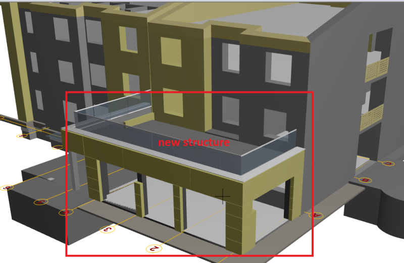
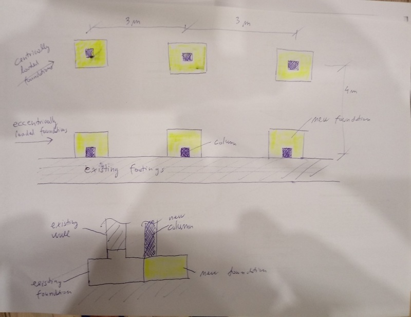
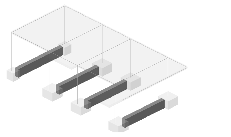
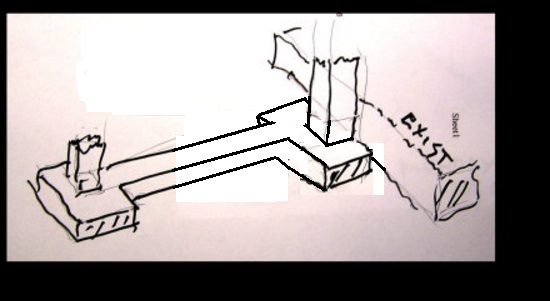
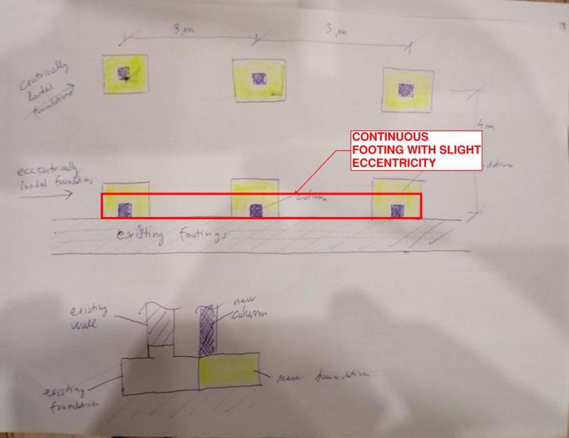
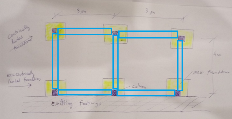
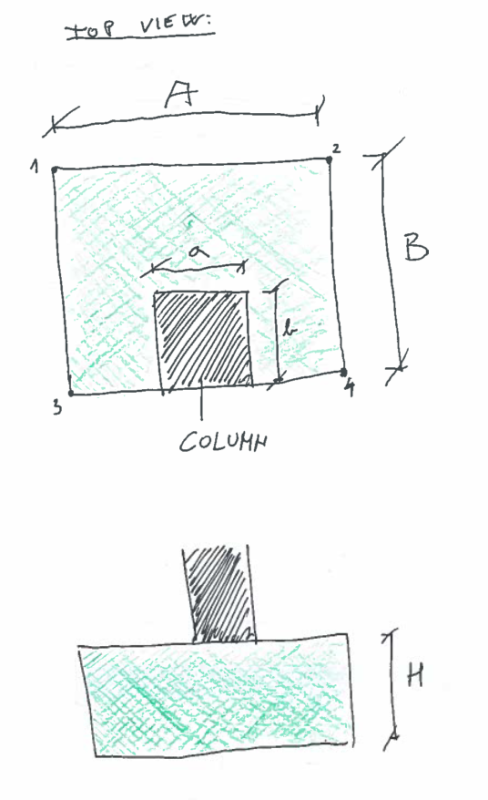
I have an eccentrically loaded single foundation (sketch bellow). A column is on the edge of foundation since there is an existing structure right next to it. I want to calculate contact pressures under a foundation in point 1, 2, 3 and 4. I havent done this in years and I cant find my equations...Any help?
thanks.


tt_a2ypif.png
 
Replies continue below

Recommended for you

Unless the footing has a large mass of its own, any dimension of B larger than b doesn't help reduce the maximum soil pressure.
 
You also will affect the adjacent foundations. One always runs the risk of causing adjacent foundations to settle some since both foundations make use of soil below the joint zone.
 
Thanks for replies.

What do you guys suggest I do here? i have new structure next to existing. New single foundations next to existing foundation are eccentrically loaded. Should I connect single foundations with foundation beam (i dont know what is a proper expression in English)?
is there another/better way?

1b_zbakha.png


1aa_kpurfm.jpg


1c_sojypl.png
 
If you can work out the load on the existing foundation wall, could you dowel the new foundation into the existing foundation and verify that the combined load is adequate? You could roughen the existing foundation vertical face to increase shear transfer between the two as well. Differential settlement may be of some concern.
 
@oldestguy thank you for your sketch, but i do not understand why did you sketch a single foundation in the middle of a foundation beam instead at the end right next to existing foundation (where column actually is)?

connecting eccentrically loaded foundation with centrically single foundation with a RC beam seems to be a way...


1d_omcydp.png
 
OG is telling you to move the footing away from the existing building and design your grade beam (foundation beam) as a cantilever to pick up the column. This removes the eccentricity from the equation if you put the footing below the beam and helps with not affecting the existing foundations.

His recommendation is the way you should be doing it.
 
thanks for explanation. I have never seen something like this. Im wondering... i suspect that grade beam is pretty strongly reinforced in this case since there are transfer of bending moments from column to grade beam, right? OR im also asking myself should i really use fixed support for connection column - grade beam (foundation) in this case? I think connection in model should be pinned - especially in direction perpendicular to grade beam, so the only force from column to grade beam is compression and horizontal normal , but no moments.
 
Most designers start with a pinned base assumption to remove the complication. Only going to fixed base where absolutely necessary.

However keep in mind that it will not be truly pinned, nor will it be truly fixed, but rather somewhere in between. Your joint detailing will play a huge part in which assumption is more correct. The foundation beam should be designed for some moment transfer from the column, however the column and frame structure above should be designed as if the base were pinned.
 
I've mostly seen this done per mats12's last sketch rather than OG's. I'm guessing that's because:

1) Having the footing closer to the load generally makes for a cheaper arrangement.

2) In my experience, it's rare that you'd be able pull the footing so far back that its zone of settlement influence wouldn't still impact the existing building anyhow.

3) In pulling the footing back, leverage increases the load delivered to the footing. So, in a non-linear manner, the extra load is kind of undoing what was accomplished by pulling the footing back in the first place. At least this would be the case for the modest setbacks that I'd typically expect to see.


I like to debate structural engineering theory -- a lot. If I challenge you on something, know that I'm doing so because I respect your opinion enough to either change it or adopt it.
 
OG again. Really for a light building it may not be needed to do anything special. Taking loads into consideration and knowing soil settlement properties and computing resulting settlement effects would be the best way to decide any of this.
 
Would there be some advantage to making the discrete ftgs. along the existing strip ftg. a strip ftg. also, or a wide grade beam? This would lessen the eccentricity affect somewhat and spread the col. loads out along the existing ftg. line, in a more uniform fashion, and at a lower kips/sq.ft. soil loading.
 
Why not a continuous footing that may have a slight eccentricity? You can model it in any FEA program of your choosing (RAM Concept would be my choice) and find the exact pressure distribution.

1aa_kpurfm_q2kmf0.jpg
 
I was thinking about making a new continuous footing right next to existing footing, but isnt it true, that single foundations setlle less than strap footings? Because pressure can be destributed on all 4 sides of single foundation but only on 2 sides when it comes to strap footing? But since i do not have continous load (wall on footing) but columns, that may not be the case?


I was thinking about connecting single foundations with strap footings in all directions. So the eccentricity can be transfered through strap footing.

111_e5zz3b.png
 
This is the way I would do it. Model support of the grade beams with line spring to get more realistic moment distribution and also contact pressure. In this way eccentricity is near zero and you can model without it.
 
@molibden thats what I had in mind. But as far as modeling of strap beams go (dimension 300 x 600 m), I read that you should model them as rigid and not supported (no line spring). Anyone knows why is that? If I model strap beams as rigid and unsopported I get much bigger single foundations (900 x 900 mm instead of 700 x 700 mm). I think that method/model is kinda conservative since it doesnt consider that there will also be contact pressures under strap beams... I think I ll do as molibden proposed.
 
mats12,

You should model the south continuous footing (the one against the existing building) as a footing supported on soil.

If you can get this to work with a slight eccentricity (you should be able to do that since it appears to be only one story), then just use isolated footings on the north column line and you're done.

If you can't get that continuous footing to work, add straps going north-south to the north column line footings. The purpose of that strap is to counteract the eccentricity of the south column footing with the weight of the strap. You can find a good reference for this in the Structural Engineering Reference Manual that a lot of people use for studying for the SE exam. Technically you're required to leave a gap between the strap and the soil. I often see some sort of compressible material there (and sometimes soil...).

The east-west continuous footing at the north column line you show isn't really necessary if you keep the isolated footings at that column line.
 
I provided some extensive strap footing help a while back in another thread that may be helpful. See the sketches near the bottom: Link

I like to debate structural engineering theory -- a lot. If I challenge you on something, know that I'm doing so because I respect your opinion enough to either change it or adopt it.
 
Status
Not open for further replies.

Part and Inventory Search

Sponsor