Continue to Site

Eng-Tips is the largest engineering community on the Internet

Intelligent Work Forums for Engineering Professionals

  • Congratulations waross on being selected by the Eng-Tips community for having the most helpful posts in the forums last week. Way to Go!

Dynamic Analysis of an Elevated Frame Foundation for Pumps

Status
Not open for further replies.

oengineer

Structural
Apr 25, 2011
732
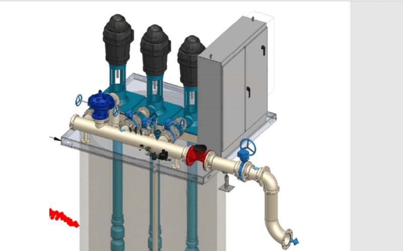
I am working on the design of 3 pumps siting on top of a circular slab of a wet well.

In PIP REIE 686, it states that "A dynamic analysis of an elevated frame foundation(table-top foundation) shall be required to demonstrate that the natural frequencies of the foundation do not coincide with and are separated from the operating speed range of the equipment by at least 20 percent. The foundation design for variable-speed equipment will require that the foundation be checked for resonant frequencies through the entire range of operating speeds."

Would anyone happen to know a technical document that has an example of performing a dynamic analysis for a table top foundation?

PIP REIE 686 states: A “table-top foundation” is an elevated three-dimensional reinforced concrete structure that consists of large beams or a thick slab connecting the tops of the supporting columns. The mechanical equipment is supported by the large beams or the slab located at the top of the structure.

Suggestions/comments are appreciated.

 
Replies continue below

Recommended for you

I have uploaded the plan, elevation, and isometric view of the Pump Skid that I need to provide a foundation for in relation to the Wet Well in the following link:

I have confirmed with the vendor that the skid shall be design to resist all the dynamic loads/forces caused by the pumps mounted on top of them.

My issue now is to provide a foundation design for the pump equipment skid. The issue is it seems that I will need to have a large hole inside my skid foundation.

What is the best way to tackle this type of skid foundation design? What is best practice?

Suggestions/comments are appreciated.
 
Yes, it should help, but you still need to perform dynamic analysis if it is called for. I'm more interested to see how you place the skid, as it is larger than the wet well in the sketch. Also, does the wet well require maintenance, worker entrance?
 
retired13 said:
Yes, it should help, but you still need to perform dynamic analysis if it is called for. I'm more interested to see how you place the skid, as it is larger than the wet well in the sketch. Also, does the wet well require maintenance, worker entrance?

I would think that since the skid is not being supported by the wet well, that a dynamic analysis is not required anymore. Since the vendor has told me that the skid shall be design to resist all the dynamic loads/forces caused by the pumps mounted on top of them. To me, this means that this situation is not a table top design, but just a skid equipment foundation.
 
Sounds good, just double check that no vibration will passing through the skid. But how about the skid is outsized the wet well, maintenance issue, etc..?
 
retired13 said:
But how about the skid is outsized the wet well, maintenance issue, etc..?

I am not sure I understand this question.

Also, even though if believe a dynamic analysis is not needed for the top slab of the wet well, I am still seeking information of possibly designing a circular skid foundation.

Or would it be possible to design block support at each corner of the skid?

I am open to suggestions/comments.
 
Look at the sketch below. It seems the skid width "B" is the same as the "D"iameter of the wet well. Yes, you need some corner detail so the skid will be sat in comfortably. The wet well looks like to be fully covered by the pump system, if maintenance access is required, how the cover slab is to be uncovered/liftoff? These are the details I'm concerned with.

p_pgmgta.png
 
retired13 said:
It seems the skid width "B" is the same as the "D"iameter of the wet well. Yes, you need some corner detail so the skid will be sat in comfortably. The wet well looks like to be fully covered by the pump system

I think I see what you're saying now.

I actually cannot believe that I didn't realize it sooner, but since the actual outer diameter of the wet well is 10'-6" (126"), the skid as shown will have to be mounted to the top of the wet well.

Only other option I can think of is to request that the skid vendor increases the foot print of the skid to be much greater than 126".

Or, then the situation that I have is a "table-top" dynamic design condition.

[ I was mainly look at this picture provided by the vendor, instead of what is actually going to be built. I am glad I caught it now. ]
 
Has anyone ever come across this type of situation before regarding a pump skid foundation?
 
I think for a small wet well with so many pumps, you may be better to set pumps bedside the well rather that top. However, this arrangement may change pump efficiency and require mechanical changes for a different type of pump (90° vs vertical). Can you make the call?
 
retired13 said:
I think for a small wet well with so many pumps, you may be better to set pumps bedside the well rather that top. However, this arrangement may change pump efficiency and require mechanical changes for a different type of pump (90° vs vertical). Can you make the call?

I cannot change the location of the pumps. They need to be above the wet well. This has been determined by the civil engineer.

The link below shows the current configuration of the pump skid on top of the wet well. The 108" x 99.25" box represent the pump skid & the 3 boxes inside the wet well circle represent the location of the 3 pump:
Would this situation be considered a "table top" situation regarding the pumps, based on PIP REIE 686?

Would it be acceptable to just design the top slab of the wet well for 3 times the weight of the pumps?

Is anchoring the pump skid to the wet well an option?

 
1) Your system will never be classified as a "table top" system, which is characterized as heavy dynamic equipment supported by a massive foundation that is free to swing in lateral directions.
2) If there is nil, or minimal, dynamic/vibration effects, you only need to design the slab for slab self weight, the operation weight of the pumps, and service load, if any. The slab should be thick enough to allow the placement of anchorages, if required.
3) Again, as addressed in 2 above, you can directly anchor the skid to the wet well, that has adequate thickness.

If concrete slab is provided, make sure it can be removed for maintenance access.
 
JoelTXCive said:
How many horsepower are the pumps? And do they run full time. And are there workers that are going to be there full time subjected to the vibrations?

If they are less than 200hp, and the answer to the other questions are 'No', then it's probably easier to skip the dynamic analysis and use ACI's "Rule of Thumb Method (yes, that's the real name). Thicken the top slab to get a 5 to 1 mass ratio of concrete to your equipment.

Their are 3 pumps resting on top of the Wet Well top slab.

Each pump weighs 1,583 lbs. Each pump has a power rating of 1800 RPM. Each pump has an operating speed of 40 HP.

The total pump weight is then 4,749 lbs for all 3 pumps. The total power rating for all 3 pumps 5400 RPM. The total operating speed for all 3 pumps is 120 HP.

I ended up increasing the circular slab diameter to 11'-0" with a thickness of 15 inches. My actual weight ratio is 3.71. This weight ratio also includes the subtraction of the opening of the pumps through the top slab.

PIP STC01015 Structural Design Criteria states that "Unless specified otherwise by the equipment manufacturer, for grade mounted centrifugal machinery 500 horsepower or less, in the absence of a detailed dynamic analysis, the foundation weight shall be designed to be at least three times the total machinery weight. Weight of a grouted equipment skid can be considered part of the foundation weight for this provision."

PIP STC01015 also states,"Support structures or foundations for centrifugal machinery greater than 500 horsepower shall be designed for the expected dynamic forces using dynamic analysis procedures."

Based on this criteria it would appear that the wet well top slab is acceptable. Especially since all 3 pumps added together is less than 500 HP.
 
retired13 said:
1) Your system will never be classified as a "table top" system, which is characterized as heavy dynamic equipment supported by a massive foundation that is free to swing in lateral directions.
2) If there is nil, or minimal, dynamic/vibration effects, you only need to design the slab for slab self weight, the operation weight of the pumps, and service load, if any. The slab should be thick enough to allow the placement of anchorages, if required.
3) Again, as addressed in 2 above, you can directly anchor the skid to the wet well, that has adequate thickness.

If concrete slab is provided, make sure it can be removed for maintenance access.

@retired13

Do you agree with the paragraph below? Based on the information provided.

Their are 3 pumps resting on top of the Wet Well top slab.

Each pump weighs 1,583 lbs. Each pump has a power rating of 1800 RPM. Each pump has an operating speed of 40 HP.

The total pump weight is then 4,749 lbs for all 3 pumps. The total power rating for all 3 pumps 5400 RPM. The total operating speed for all 3 pumps is 120 HP.

I ended up increasing the circular slab diameter to 11'-0" with a thickness of 15 inches. My actual weight ratio is 3.71. This weight ratio also includes the subtraction of the opening of the pumps through the top slab.

PIP STC01015 Structural Design Criteria states that "Unless specified otherwise by the equipment manufacturer, for grade mounted centrifugal machinery 500 horsepower or less, in the absence of a detailed dynamic analysis, the foundation weight shall be designed to be at least three times the total machinery weight. Weight of a grouted equipment skid can be considered part of the foundation weight for this provision."

PIP STC01015 also states,"Support structures or foundations for centrifugal machinery greater than 500 horsepower shall be designed for the expected dynamic forces using dynamic analysis procedures."

Based on this criteria it would appear that the wet well top slab is acceptable. Especially since all 3 pumps added together is less than 500 HP.
 
I think I can agree on the way you handle the mass and power, but combining the speeds in comparison. Since the pumps look like rotary type, so you are in the right path to have the slab weight at least 3 times of the combined pump weight. But ultimately the thickness needs to be verified by the vendor furnished reactions, and dynamic characteristics of the pumps in operation.
 
retired13 said:
....but combining the speeds in comparison.

Could you please elaborate on the issue you have with the speed being combined?

The speed is still less than 500 HP with all of the pumps combined.
 
"rpm" (revolution per minute) is a measure of rotational speed, and "HP" (horse power) is a unit of measurement of power, or the rate at which work is done. When I say "I can agree on the way you handle the mass and power", it was based on the assumption that these pumps arranged and operate in series, not in parallel. I think you shall find and go over some examples on design of dynamic/vibratory machines, if you are interested in this topic.
 
Status
Not open for further replies.

Part and Inventory Search

Sponsor