Tek-Tips is the largest IT community on the Internet today!

Members share and learn making Tek-Tips Forums the best source of peer-reviewed technical information on the Internet!

  • Congratulations cowski on being selected by the Eng-Tips community for having the most helpful posts in the forums last week. Way to Go!

Drawing - help lines aligned with object

Status
Not open for further replies.

mtweeman

Mechanical
Joined
Jan 17, 2012
Messages
7
Location
PL
Hello!

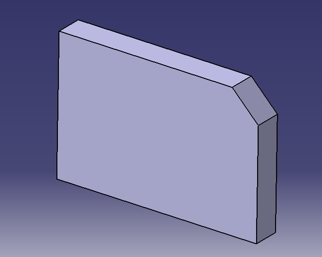
I have a simple CATIA part:
file_1_iaq1vh.jpg

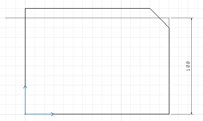
On the drawing I want to measure dimension using some additional point at "virtual" corner:
file_2_t5pxqd.jpg

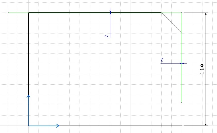
However, if I change one of dimensions, additional line stays in place it was put:
file_3_rppvux.jpg

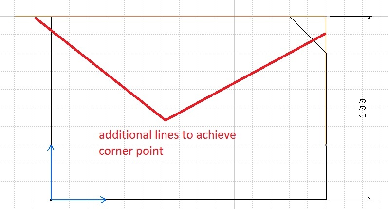
I can draw additional lines to achieve this corner and use drive geometry to make them aligned to part side lines:
file_4_phrbch.jpg


Is there any way to avoid this way and use some CATIA built-in features to achieve such result?

Thanks in advance!
 
Yes, you can use the 'Intersection Point Detection' functionality on the 'Tools Palette' toolbar that appears when you initiate the Dimension command. This will create an associative link to the geometric elements.

This will also prevent the need to produce any secondary geometry.

--Doug
 
Thanks! This is what I was looking for!
 
Maybe additional question: is there any way to show lines that create this intersection points? I mean show them on final drawing.
 
mtweeman,

When creating distance dimensions, always dimension between lines. If you select the top and bottom lines you will avoid the problem in your first post, plus the extension lines will always be long enough.
 
Status
Not open for further replies.

Part and Inventory Search

Sponsor

Back
Top