Alberto Ramirez
Automotive
Good Day,
I have this question that is confusing me.
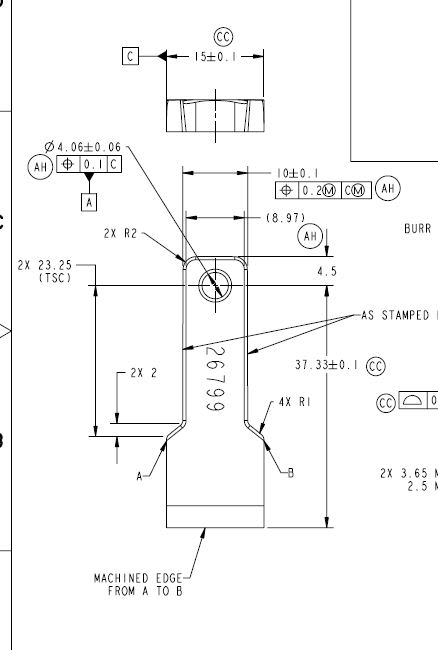
On the following drawing there is this CC - 15 ± 0.1 (Datum C)
According with the designer, this part has a draft, he make reference to a "Drafting standards - ASME Y14.5"
Where he indicates that the feature doesn't control size and form, this mean, part can be out of spec, dimension and tolerances not apply on draft part.
For more explanation see ppt attached.
According with the drawing there is not a draft tolerance and because "Drafting standards" allow to be out of spec.
On cad there is not draft specified either.
In your experience, how this should be interpreted.
Thanks!
I have this question that is confusing me.
On the following drawing there is this CC - 15 ± 0.1 (Datum C)
According with the designer, this part has a draft, he make reference to a "Drafting standards - ASME Y14.5"
Where he indicates that the feature doesn't control size and form, this mean, part can be out of spec, dimension and tolerances not apply on draft part.
For more explanation see ppt attached.
According with the drawing there is not a draft tolerance and because "Drafting standards" allow to be out of spec.
On cad there is not draft specified either.
In your experience, how this should be interpreted.
Thanks!