Continue to Site

Eng-Tips is the largest engineering community on the Internet

Intelligent Work Forums for Engineering Professionals

  • Congratulations waross on being selected by the Eng-Tips community for having the most helpful posts in the forums last week. Way to Go!

Double Envelope Worm

Status
Not open for further replies.

jacek0841

Mechanical
Aug 31, 2005
227
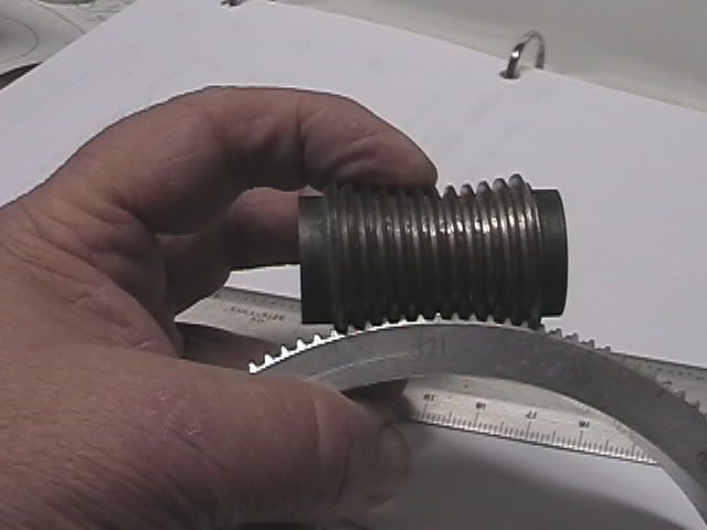
Is it possible to "cut" Double Envelope Worm in SolidWorks ?

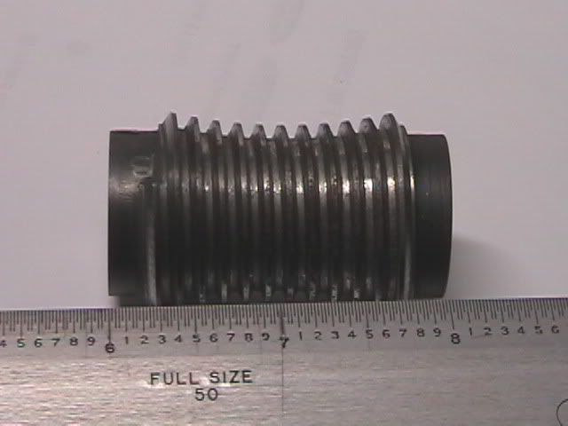
Basically, the worm blank is not a problem - just a simple revolution of part of a circle, ends closed up with straight lines.

Now comes the hard part - how do you machine the "groove" (tooth) ?

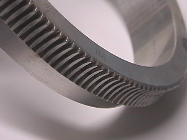
I would imagine to put a "triangular" cutter (which symbolizes a tooth from the worm gear) rotating at a constant angular speed (because the Gear rotates at constant angular speed). The center of the rotation would obviously be the center of the Worm Gear.

The Double Envelope Worm also rotates at a constant angular speed.

So if you somehow tie up both speeds (ratio !) and "enter" the cutter into the rotating Worm, it would "machine" the "groove" (tooth) in the Worm.

I guess that much of the teory, but can you do it in SW2006 ??

Any hints ??
 
Replies continue below

Recommended for you

Thinking further - if I could somehow "scribble" the path on the worm blank the the rest would be "Swept Cut".

But how would you "scribble" the path ?
 
Thinking out loud ... :

The Path could be described as: Helix --> Pitch and Revolution --> Variable Pitch

The more points you put into the Region Parameters the more accurate the Path will be.

The "linear" pitch of the Worm is the biggest in the "middle" of the Worm and it continuously decreases when going to either end of the Worm, as per SIN function.

The OD. of the Worm is the smallest in the "middle" of the Worm and continuously increases as per

Y=Dist - sq.rt(sq.R - sq.X),

where: Y=rad of the Worm,
Dist=distance between CL of Worm and CL of Gear,
R=rad of the Worm Gear,
X=distance from "middle" of the Worm.

So both functions are not linear meaning "the more points, the more accurate the Path". Both, Dia and P in Region Parameters will have to keep on changing the reflect the above functions ...

I guess enough thinking for today ... maybe will continue tonight at the local Sports Bar ... :)
 
Thinking further (still in the office :-( ):

Could you somehow "drive" Dia and P in Region Parameters Table by equations ??

Because if you could, then I think writing the equations would not be that difficult ...
 
Make your path. Do this by plugging this function into excel, export the points as ascii tab delim, and then using the point import macro to bring in the xyz's. Use insert curve through reference point to create the path. Select the curve and its endpoint and create a plane. Sketch your triangle in this plane. Now you have your path and profile for a sweept cut. Use keep normal constant.

I have got more accurate results with the following method: Surface sweep a line down this path with keep normal constant. Then put a triangle surface centered on this path endpoint and perpendicular to the surface you swept it down. Use curve driven pattern with a fairly high number of instances and equal spacing to send this surface body triangle down the path. Under Alignment Method use the initial line you swept down the path as your face normal. Now create a lofted cut with all these triangle surface profiles(select show all connectors and fix them as you select them in order).

I'm not completely sure if I have achieved what you are looking to do....

RFUS
 
.
Thank you all.

Now:

... export the points as ascii tab delim, ...
You mean Excel Save As Text (Tab delimited)(*.txt) right? Done that.

... and then using the point import macro to bring in the xyz's. ...

Totaly lost here - could you please explain that - I am still learning SW.

Thanks
 
Go here and download the macro:

its not in english, but you'll see where to download it. Then unzip the .swp file.

In Solidworks go to tools-> macros -> run and select this point import .swp file. It will bring open a dialog looking for this ascii delimited point file. Select the .txt file you created, and if it is in the proper format you now have now brought your points in. Check the sample file in the zip for format if you have a problem.

Get to here and then see if you can insert curve through reference point.

RFUS
 
FirstThe stuff I have written above, that is:

... as per SIN function.

The OD. of the Worm is the smallest in the "middle" of the Worm and continuously increases as per

Y=Dist - sq.rt(sq.R - sq.X), ...

is wrong - it is more complicated than that.

Second:
Having fixed the above I then tried the stuff recommended by rfus :
... and then using the point import macro to bring in the xyz's. ...

That seems to work - 46 lines/points processed - though I got one error message (something wrong on line 11) - I think I will have to have another look at that line 11.

I haven't done the curve thruough the points yet, but the points look O.K. - at least for the moment.

Third:
I just tried something else - after opening with NotePad that *.txt file saved by Excel and inspecting it, I Saved As *.sldcrv

Next I used Curve through XYZ Points and browsed for that *.sldcrv file - et voila, I have got that curve (Path) without using the macro mentionned by rfus

Thanks everybody ... :)
 
Would you mind posting a picture of the finished gears?

O.K., provided I succed - right now I am having problem with the next step - the cut - in preview looks O.K. but when actually done, it does some funny "flip"

Will have to try some of rfus suggestions ...
 
rfus:... Use keep normal constant.

No, in my case it gives that "funny flip" I mentionned earlier. I have to use "Follow Path", still not perfect, need to orient (somehow) the "cutter" constantly "pointing" to the center of the (worm) Gear - but at least no "flip".

I guess that could be done by either two guide curves lying on the Worm (sort of "OFFSET" from the Path) or by "Direction Vector".

The last one is my wild guess because I do not know what the "Direction Vector" is (in Cut-Sweep).

Could anybody please tell me what "Direction Vector" is ??
 
Happy Thanksgiving!
I know something of the subject, here is some pictures of a set.
Have not yet tried to draw one up in SW. Done spur gears, with hob runoff, Working on helicals at the moment,
Will think on it a bit & try to get back, also have Zerol & Spiral bevels, on my back burner.


Double Enveloping Worm Gear Set

PANA0412.jpg


DOUBLE ENVELOPING WORM (SUBJECT)

PANA0405.jpg


Double Enveloping Worm Gear

PANA0403.jpg


Cheers, Les H.
 
WinstonH - are you working for that outfit in Cicero, IL. ? (I forgot the name)
 
jacek0841 (Mechanical)
No,I am retired, I used to work for a company in California, [Vard Newport Inc], Had a Hourglass grinder that the founder had built, used a J&L thread grinder head on a custom built, (including the castings) base, it also had auto backoff for grinding the hobs.

When I worked on them it had languished a few years, so I got it going again, to hob them I modified a hobbing machine with a device that allowed rotating the part after reaching full depth, (the hob has to be thinned down). The hob first cuts on the outer ends, resulting in a scalloped center on the wormgear, then the wormgear has to be rotated about .005" a side to acheive proper form, (to remove the scallop).

The pics posted were from an early turret drive for the Apache, total backlash assembled .0010" - .0025". Measuring the worms now thats another story, but very repeatable and accurate.

Cheers Les H.
 
[bold]Thoughts on cuting hourglass threads.[/bold]

A plane at left hand side, a plane in the center of the worm and a plane at the right hand side. Create a helical spiral from the center plane pitch dia terminating at each end to the pitch diameter at the ends. Then position the worm form at the center and cut from there in both directions to complete, for multiple start worms copy rotate as in cutting gears.
Honeydew calls, more later I think we can do this.

Cheers Les H.
 
Jacek0841.

So single start worm to begin, how many teeth in the wormgear, Center distance to set the pitch, etc?

I'll dig into my notes for the calculations.
Back in a while.
Les H.
 
Jacek0841.

Have been searching thru my notes, found some stuff on the Vard Grinder, but not the notes where I had blank copies of the calculation sheets from the A.G.M.A. Double Enveloping Worm document. Do you have the worm and worm gear specs for the subject?

The Vard Hourglass worm & hob grinder.
DEWG0003.jpg


A copy of the operating instructions for the Vard grinder.
DEWG0001.jpg


Another shot of the worm I have. Which will be similar to what is being discussed.
DEWNOV06A02.jpg


Yours Truly, setting up a Gleason # 29 Curvic Grinder, about 1973.
DEWG0004.jpg


Cheers Les H.
 
Status
Not open for further replies.

Part and Inventory Search

Sponsor