Continue to Site

Eng-Tips is the largest engineering community on the Internet

Intelligent Work Forums for Engineering Professionals

  • Congratulations waross on being selected by the Eng-Tips community for having the most helpful posts in the forums last week. Way to Go!

Does a fully enclosed PEMB meet the ASCE 7 definition of "Simple Diaphragm Building"? 3

Status
Not open for further replies.

1835Eng

Structural
Jul 17, 2017
7
Would a fully-enclosed Pre-Engineered Metal Building (PEMB), with continuous wall sheathing and roof, meet the ASCE 7 definition of "Simple Diaphragm Building"?
ASCE 7-16 definition is as follows:

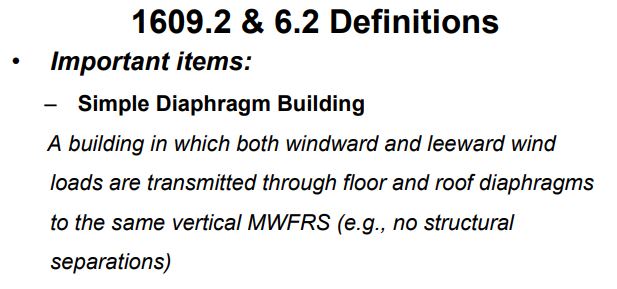
"BUILDING, SIMPLE DIAPHRAGM: A building in which both windward and leeward wind loads are transmitted by roof and vertically spanning wall assemblies, through continuous roof and floor diaphragms, to the MWFRS."

If the roof/wall panel and purlin/girt assemblies are idealized as flexible diaphragms, does a PEMB meet the criteria for the simplified procedures in Chapters 27/28? The potential hang up in the code language is "vertically spanning" wall assemblies. The panels span vertically, but transmit load to the horizontal girts which then load the building frames. Does this disqualify the metal building system from the Part 2 provisions of ASCE 7, or no?
 
Replies continue below

Recommended for you

No in my opinion since the girts deliver the loads to the frames through horizontal distribution.
 
Moreover, a PEMB has tie rods in the roof diaphragm and exterior walls to distribute the lateral forces. The roof deck is usually very light gage - 28 or 29 gage - and of little structural value. If you have a higher gage, then maybe.

Mike McCann, PE, SE (WA, HI)


I agree with msquared48; because of how a PEMB works, it would not fall into a simple diaphragm building category. To add to the comment about the decking - most PEMB roof deck manufacturers no longer publish shear capacities (most state not to be used as a diaphragm now), in fact I haven't had any luck finding any standing seam decks with shear capacities in the last few years. Out of curiosity, what are you intending to do with these loads?
 
OP said:
Would a fully-enclosed Pre-Engineered Metal Building (PEMB), with continuous wall sheathing and roof, meet the ASCE 7 definition of "Simple Diaphragm Building"?

- I vote yes.

- The real litmus test is just whether or not one can expect internal pressures to cancel out across the interior of a building where all wind pressures would be transmitted to common VLFRS elements. Your PEMB meets this criterion

- This has nothing to do with the usual, in plane concerns we have when dealing with "diaphragms". Here, we're talking about diaphragms for he purpose of out of plane loading. In the age of endless concerns over in plane diaphragm behavior for seismic etc, they really could have done with some more thoughtful wording on this.

- I can see how the "vertically spanning" business is confusing. They should probably just scrap that verbiage altogether change that to "walls transmitting their tributary wind pressures to roof and floor diaphragms that, inturn, transmit the load to common VLFRS". Alternately, one could take the frame columns themselves as being the things doing the vertical spanning. ASCE is basically travelling a convoluted path to establishing that we're dealing with a closed box wherein wall pressures make their way to roof and floor diaphragms connected to common VLFRS for wind load purposes.
 
Interestingly, find below:

1) An example from a Wood Council presentation where they've screwed this up and;

2) What would seem to be a more rational definition.

c01_m4ans2.jpg


c02_sand4d.jpg
 
Be careful with the conclusion of a PEMB being "enclosed". If it has a large roll-up or sliding door, it likely cannot meet the "enclosed" criteria.
 
Look in the ASCE 7-10 Chapter 28 Commentary.

PART 2: ENCLOSED SIMPLE DIAPHRAGM
LOW-RISE BUILDINGS

"Additionally, there should be no girts
or other horizontal members that transmit significant
wind loads directly to vertical frame members of the
MWFRS in the direction under consideration."
 
Thanks all for the input. Haynewp's post above is the confirmation I was seeking.
 
Clearly I have been wrongheaded above. As such, I retract all of my previous comments.

Like any ancient goat herder attempting to interpret the old testament, however, I want to know why. Firstly, there's the intellectual curiosity thing. Secondly, one should understand the rules prior to breaking them. Having noodled on this a bit more, I think that I now do understand the rules, and I'd like to table them for consideration.

1) Having examined the commentary, it still seems to me that the litmus test here is whether or not opposing internal pressures cancel out with respect to the loads that make their way to the MWFRS. In my previous comments, I neglected to consider some of the more detailed implications of this as they would apply to a PEMB frame.

2) From the perspective of these provisions, the roof beams of a PEMB frame are really the ultimate diaphragm. Via axial load transfer through a relatively beefy member, you'd get near perfect distribution / canceling of opposing load from one side of the building to the other.

3) Imagine an an analysis wherein one is looking at a PEMB frame and simplifying the MWFRS load as a couple of W/2's applied at the eaves of the frame. For this simplified analysis, I would say that you absolutely could use the simplified wind procedure because the intent of ASCE7 is satisfied: interior wind pressures on opposite sides of the building are collected, distributed, and cancelled as far as a macro-scopic analysis of the frame for MWFRS goes. Extending this concept, I would also say that all of the following could likely be designed using the simple diaphragm / simplified wind provisions:

a) Drift checks on the frame. No practical inaccuracy here.

b) Primary moment checks of the frame at the joints. Very little practical inaccuracy here.

c) Frame foundations. Very little practical inaccuracy here.

d) Really, the entire frame if the configuration were such that the application of reasonable judgement would lead one to conclude that primary lateral design of the frame dominated the response and that the impact of secondary, individual girt/purlin point loads was negligible.

4) The use of the simplified wind procedure would not be applicable where the impact of secondary girt/purlin point load on the frame was significant. This, for the simple reason that internal wind pressures would not cancel out on individual components of the frame (frame columns for example) even though they would cancel out for the frame as a whole. This, I believe, is where I went astray initially.

c01_mdyewn.jpg
 
5) Trying to dream up a case whereby using the simplified procedure with girts would have a very significant impact on the MWFRS, consider:

a) Braced frames instead of portal frames where girts deliver appreciable wind loads to the columns of the braced frame.

b) In the absence of the girts, the braced frame columns would see little moment.

c) In the presence of the girts, the braced frame columns would see significant moments. And there's the rub, I think.

d) Braced frame columns should definitely not use the simplified procedure in this case.

e) Again, technically, drift, diagonal braces, beams, and probably foundations could be designed via the simplified procedure. Although I can't see anybody actually going to the trouble of designing the different parts via different methods like this.

f) Contrast this example to the PEMB frame one wherein the frame would be subject to significant moments with or without the girts.
 
Status
Not open for further replies.

Part and Inventory Search

Sponsor