wrightway
Structural
- May 12, 2016
- 5
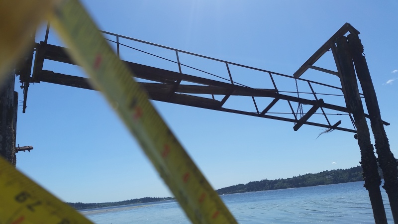
i made a thread the other day and it seems it got deleted, anyways i went and looked at this ramp and the structure was different than what the guy told me, I know how to calculate the strength of the base frame but im not sure how much the upper portion adds to the structure, so here is the dimensions and the numbers i got
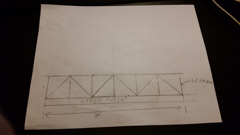
the ramp is
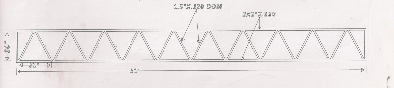
24" wide
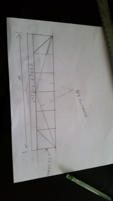
30' long
30" tall railing with vertical supports every 5ft
2 frame railes are c5x6.7:7.48 in4
the railing and handrail are 1.5" .120 dom
and on each side there are 2 5/8 all threads that go to the center
the load i calculated is .04kip/ft which should give me a = load across the ramp of 2500lbs
i am not sure what the upper frame adds for support tho
the ramp is
24" wide
30' long
30" tall railing with vertical supports every 5ft
2 frame railes are c5x6.7:7.48 in4
the railing and handrail are 1.5" .120 dom
and on each side there are 2 5/8 all threads that go to the center
the load i calculated is .04kip/ft which should give me a = load across the ramp of 2500lbs
i am not sure what the upper frame adds for support tho