Well koushik123,
while I'm more then happy to help, were I can, I'm not going to provide you with a complete layout of an damper dyno, you will need to put some thought and effort into this as well.
Some things to consider.
Depending on what you want to do with this machine (you haven't eluded on to this much so far), you may want to first decide what kind of drive mechanism to use.
I know, that you said, you are going for a crank drive - which is fine, I just want to point out, that a crank drive dyno, will not produce a true sinusoidal (cos) function, but a so called scotch-yoke drive would. This in itself, isn't a big deal, just be aware of it, and based on your expectations/aim chose a appropriate stroke/conrod ratio, if you want to go with an crank dyno.
Most (not all) commercially available dynos these days make use of the scotch-yoke drive (unless they use hydraulic rams or linear drives, but this is a totally different class of dyno). To see the differences, you may want to have a quick look at these links.
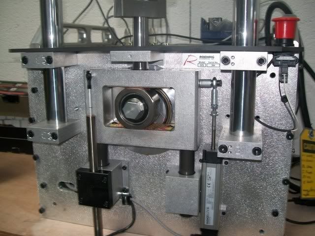
Here is a photo from a commercially available dyno, quite popular within the racing community, featuring a scotch-yoke drive.
Furthermore, you see the sensors for displacement and velocity in this photo.
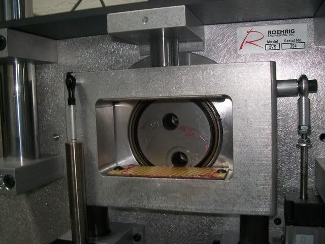
detail of the scotch-yoke
now coming back to your question:
As always it depends on what you want to do, what you have at hand and what your budget is.
You need to have an idea, which forces your damper is going to produce and then chose a appropriate bearing size.
If you want/need to build a really low cost dyno, you could go and use an old conrod from an engine and the piston pin as well, so you would have one side of the crank mechanism sorted out.
I would use roller bearings for the conrod to crankshaft and conrod to slider attachments. Nothing fancy, just double sealed roller bearings of an appropriate size. ( I know, that you can make an argument, that this is not the best arrangement for the conrod to slider connection, because the bearing will not make a complete turn, same argument as for suspension rockers, nut I will leave it to others to argue this case. I know that it works on a practical level)
As bearing for the slider, you can either choose a plain PTFE bearing, like you find in most McPherson upside down struts or motorcyle forks (
- low cost option would be to use a Bilstein 40 mm strut/damper tube with the assorted strut bearing (get for a couple of bucks from your wrecker) or similar
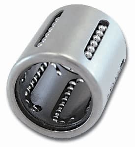
or, and that would be my choice, and is quite common in commercial dynos, these days use a "linear bearing" complete with assorted hardened guide/bar.
Keep in mind, that if you use a linear (roller) bearing, your slider needs to be hardened, otherwise it wont last long. But you can buy this "off the shelf" - no big deal/cost today.
As I said before, it's not very common, to mount the crank drive directly onto the motor. Most dynos, will either use a "gearbox" - not many or and this is a very common layout use a tooth belt drive to drive the main "crank-shaft".
Therefore you would need at two (roller) bearings more for the shaft - nothing fancy.
Other thinks to consider.
Try to use a "low displacement" load cell (pancake type) vs. an S or Z shaped one. (it's a bit more expensive but worth the investment - IMHO)
If you are pedantic, consider to mount the displacement (and velocity) sensor(s) parallel to the damper/shock you test, if you want to measure "true" damper/shock displacement/velocity. (most dynos measure only slider displacement/velocity)
Otherwise the deflection of your load cell/load frame may create an error in your measurements.
How large this error is, depends on the quality/integrity/stiffness of your dyno --> see comment on the load cell recommended, and what you are trying to do with your dyno, what is important to you.
This becomes more an issue with low stroke/high frequency measurements/analysis.
good luck