Circumferential Non-Uniformity in Temperature Distribution and Resulting Deformation in Jet Engines
1. Circumferential Non-Uniformity in Temperature Distribution
In jet engines — especially in the turbine section — the temperature field is
ideally expected to be
uniform circumferentially around the engine centerline. However, in practice, due to various reasons like:
- Non-uniform combustion (hot streaks from burners)
- Secondary airflows (cooling air leaks, purge flows)
- Disturbances from upstream components (like distorted flow from compressors)
- Manufacturing tolerances and operational wear
the temperature field
varies as you move around the circumference at a fixed axial location.
This non-uniformity is often called:
- Hot streaks (regions of locally higher temperature)
- Cold sectors (regions of locally lower temperature)
Typically, these circumferential differences can be on the order of
tens to hundreds of degrees Kelvin, depending on operating conditions.
2. Mechanisms Leading to Temperature Non-Uniformity
- Combustor Pattern Factors: In annular combustors, even if designed symmetrically, imperfect fuel-air mixing leads to discrete "hot spots."
- Cooling Flows: Turbine blades and vanes are film-cooled. The coolant might not be perfectly uniform, causing local cold regions.
- Burner Misalignment or Malfunction: Faulty nozzles or injectors create localized rich or lean zones.
- Thermal Boundary Layers: Differences in the cooling efficiency along casing or hub walls can create temperature gradients.
3. Resulting Deformation Phenomena
Now, non-uniform temperatures cause
non-uniform thermal expansion in engine components.
Key phenomena include:
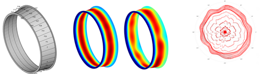
3.1 Thermally Induced Ovalization ("Thermal Bowing")
- Turbine casings, disks, and rotors, which are typically circular, can deform into an oval shape due to uneven expansion.
- Hot sectors expand more → pushing the casing outward locally.
- Cold sectors expand less → staying closer to original dimensions.
This ovalization leads to
variations in tip clearances between blades and casing around the circumference, impacting efficiency and potentially causing rubs (physical contact).
3.2 Rotor Disk "Tilt" and "Wobble"
- Non-uniform heating across the disk face can create disk coning or wobble, where the rotor hub gets displaced axially and radially.
- This introduces unwanted vibrations and can accelerate fatigue damage.
3.3 Creep and Material Fatigue
- Areas under higher temperatures creep more (plastic deformation over time), leading to out-of-roundness even when the engine cools down.
- Fatigue cycles are exacerbated where temperature gradients cause large thermomechanical stresses.
3.4 Thermomechanical Stress
Thermal non-uniformities cause
localized stresses because different parts of the component try to expand differently, but are mechanically connected:
- In extreme cases, this stress can cause cracks, especially at cooling holes or blade roots.
- In disks, it can also drive Low Cycle Fatigue (LCF) or Thermal Mechanical Fatigue (TMF) failure modes.
4. Engineering Mitigation Strategies
To control circumferential temperature non-uniformity and deformation effects, engineers design:
- Advanced combustors with better fuel-air mixing (e.g., lean-premixed, pre-vaporized combustors).
- Careful cooling flow management: optimizing the distribution and flow rates of coolant air.
- Flexible components: casings and mounts that can accommodate thermal growth.
- Tip clearance control systems: using active clearance control with cooling air to shrink or expand the casing dynamically.
- Thermal barrier coatings (TBCs) to equalize surface temperatures.
 . so is anybody knows how to deal with this kind of problems? maybe we can discuss it?