Continue to Site

Eng-Tips is the largest engineering community on the Internet

Intelligent Work Forums for Engineering Professionals

  • Congratulations cowski on being selected by the Eng-Tips community for having the most helpful posts in the forums last week. Way to Go!

Determining the load in a diagonal brace in a steel frame?

Status
Not open for further replies.

Redacted

Structural
Mar 12, 2016
160
Hi there,

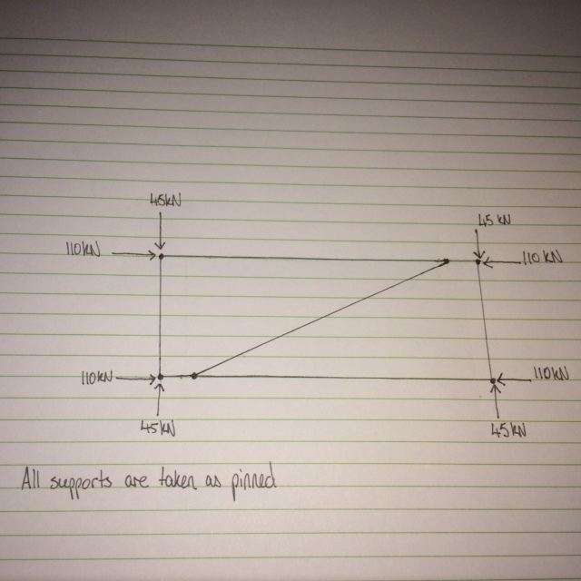
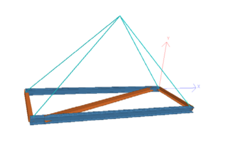
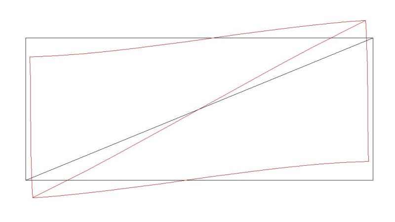
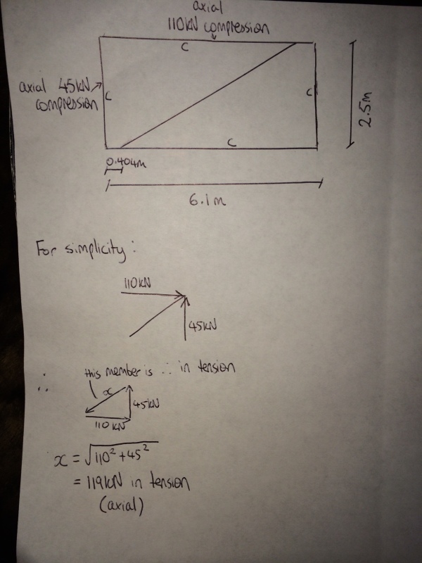
I am trying to determine the axial load in a diagonal brace in a frame. I thought the method to calculate the load would simply be as shown in the attached image, which gives an axial tension load of about 120 kN. However when I modelled the same frame in Staad pro to verify, it only gave me an axial compression force of 0.6 kN for the bracing member. The Staad pro model gave the same results as my hand calculations for the axial compression loads of the external frame members, just not the bracing member, which is why I am a bit confused. Any help would be appreciated.
image-14_v8jkir.jpg
 
Replies continue below

Recommended for you

Without knowing the stiffness of the members you cannot work it out, I would hazard a guess it's statically indeterminate so cannot be solved by simple equilibrium alone (though have not put much thought into this!).

I fail to see in any arrangement like this how you would ever get a tension load in the brace.
 
Perhaps you entered the wrong boundary conditions in Staad. If the upper two joints are free to translate laterally and the frame is responding to an applied horizontal load acting on the upper left joint toward the right, the diagonal member will be in tension as you have shown in your hand calculations. In that case, the left hand column would not be in compression.

If the frame is responding to an applied vertical load on each column, the diagonal member will tend to be in compression but the upper beam will not have a compression of 110kN.

You need to show the applied forces on the frame and ensure that each joint has the appropriate degree of freedom.

BA
 
If it is only resisting the vertical load shown, then Staad is correct in my eyes. The brace is not there for vertical loads but rather stability of the structure as a whole and to resist any lateral loading.
 
Thank you for the responses. It appears that my hand calculations were most likely incorrect for the OP load configuration (although I think it can be taken as the extreme cases for compression and tension) and the bracing force given by Staad was correct. The scenario shown in the OP has axial equal forces acting in the parallel members, which is most likely why there is almost no load in the bracing member(it seems to be redundant in this perfect scenario). When I changed the load cases to have varied axial loads acting on the members the bracing load did increase and depending on the load configuration did change from being in tension to being in compression.
 
You've forced us to make way too many assumptions about what you are trying to do (support conditions, member end releases, where loaded, member sizes) but here is a scenario where the diagonal comes close to your calculated value.
Brace_Frame_ajsrpk.jpg
 
image1-2_gs2uxj.jpg


^ For the avoidance of doubt. The axial compression forces are acting on each member as shown above and the supports are all pinned.
 
If the supports are at the four corners of the frame then the supports would get the loads and the members would not get any load. If this is a free floating frame, i.e.; you built this frame then laid it down on a sheet of ice, then applied the loads to the four corners, assuming all of the members are the same area and Young's modulus, the "brace" member wouldn't see much load. I can't imagine a real world problem quite like this. Is this a homework problem?
 
@dozer I agree it is quite a strange problem given the orientation of the frame. It is not a homework problem. The frame is actually being lifted up by 4 cables. There is a downward load at each of the 4 corner nodes (110kN). The lifting cables are causing all of the external members to be in compression.

Screen_Shot_2016-03-15_at_18.56.21_eghesi.png


When I modelled it, the only support I included was at the vertex of the cables (as a pinned support).

I ran a few load cases and only seemed to get a force in the bracing member when the corner loads were unbalanced (i.e. two corners having higher downward loads than the other two) and cause the frame to tilt. I was getting max approximate loads in the bracing member of about 50kN compression and tension depending on which side of the frame tilted. Although I somewhat trust the outputs that STAAD is giving me for the bracing loads I would still like to learn a method to double check using some form of hand calculations.
 
RStars said:
For the avoidance of doubt. The axial compression forces are acting on each member as shown above and the supports are all pinned.

The above statement does not remove all doubt. Where are the supports? If each of the four corners is deemed to be a pinned support, then there are no forces in any of the members.

Alternatively, if every joint is pinned, the structure is unstable.

There should be one pin and one roller and the two beams must be continuous with the diagonal pinned to them.


BA
 
Just saw the last post clarifying the supports. If the beams are continuous, there will be a force in the bracing member when the loads are balanced, but it will be small.

BA
 
@BAretired The beams are bolted together (4 bolts each corner). Ok your response seems to back up what the Staad output file was saying.
 
OK, it's making more sense now. This is like my free floating example. Look at the node at the end of the brace on the left side. You've got 110 kN coming in on its left and 110 kN coming in the opposite direction on its right so the forces balance. Therefore there is no force in the brace.

For an unbalanced situation like you mentioned you need to run a nonlinear analysis. I made up some numbers and tried it myself and much to my surprise the deflections actually made sense. There was still no significant load in the brace (under 1 kN). I had to cheat a little bit and give the slings some bending stiffness to keep it stable but they didn't pick up much moment. Maybe if I would have used more steps or put in some soft springs might could have got it to work without doing this, but, hey, what you want for nothing?
 
dozer said:
OK, it's making more sense now. This is like my free floating example. Look at the node at the end of the brace on the left side. You've got 110 kN coming in on its left and 110 kN coming in the opposite direction on its right so the forces balance. Therefore there is no force in the brace.

Hmmm. What you say makes sense, so if there is no force in the diagonal brace, it rotates slightly in plan and the frame racks slightly to compensate for the axial shortening of the outer members, i.e. the corners are no longer right angles.

BA
 
If the diagonal brace was positioned precisely at the two corners instead of the small offset, all five members would be stressed in compression.

BA
 
BA, that's what I thought to but it didn't happen. You're exactly right about the racking. It still happens when you run the brace to the corners. Think of this, the forces in the slings are all the same so the force that gets resolved into the beam with no brace in its corner has to be the same as the force that gets resolved into the beam with a brace in its corner. That means there is still no force in the brace. I don't know if I explained that very well. I can see it in my mind's eye but I'm having a hard time explaining it.

Here's an exaggerated view of the frame racking even when the braces go to the corner. I'm impressed that you figured that out.
Racking_rvp7as.jpg
 
I believe there is another consideration. The center of gravity of the frame remains the same before and after the frame racks, directly below the suspension point. As racking proceeds, the slope of the cables supporting the braced corners will be shallower than those on the unbraced corners. The horizontal component of force at the braced corners will be greater than that of the unbraced corners. The unbraced corners will drop below the braced corners so that the four corners are no longer in the same plane.

I believe that this is a secondary effect and will result in a very small compressive strain in the diagonal bracing member.

BA
 
When the load on the frame is unbalanced, its center of gravity (cg) will end up directly below the suspension point and the structure will rotate and translate as required to keep it there. The force and slope of each cable could be determined for any location of cg and the member forces could be calculated from that.

BA
 
Status
Not open for further replies.

Part and Inventory Search

Sponsor