Tek-Tips is the largest IT community on the Internet today!

Members share and learn making Tek-Tips Forums the best source of peer-reviewed technical information on the Internet!

  • Congratulations cowski on being selected by the Eng-Tips community for having the most helpful posts in the forums last week. Way to Go!

Determining Effective Width

Status
Not open for further replies.

cal91

Structural
Joined
Apr 18, 2016
Messages
294
Location
US
Often I have to come up with an "effective width" to check a connection capacity. In determining the effective width, I feel like i'm doing just slightly better than just pulling a number out of a hat.

Here's a real application I am working on right now that made me post this:

A lateral load being resisted by a W18 beam's bottom flange.

beam_fjtmzw.jpg


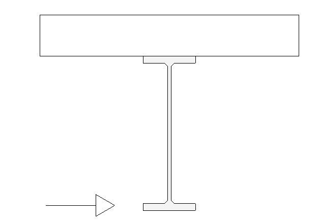
If the load is light enough, I will justify the web resisting the moment (force times 18") in weak-axis bending (section modulus taken as effective width * thickness^2 / 6). Thinking a 1 to 1 force distribution is logical, the effective width would be 18" * 2.

Does this seem practical, and do you guys do the same? Don't want to go too far out on a limb with my "engineering judgement".
 
I would do the same assuming that you're considering the top of the beam rotatiomally restrained. In bearing applications which are admittedly not the same thing, you get to take a 1:2.5 distribution. But, then, with Whitmore, we go 30 degrees. AISC's design guide on extended end plates might be a good source to check. Lotsa yieldlune stuff there.


I like to debate structural engineering theory -- a lot. If I challenge you on something, know that I'm doing so because I respect your opinion enough to either change it or adopt it.
 
Anywhere from 2(V):1(H) to 1(V):1(H) is common from what I have seen. You might take a look at this paper for some ideas (not strictly applicable, but similar). In reality I think your bottom flange will allow you to grab a lot more effective width than the typical rules of thumb would suggest.

If the lateral load is occurring along the length of the beam, my preference is to span the bottom flange between regularly spaced kickers or roll beams. This keeps the deck from having to resist the applied moment which would require reinforcing for the negative moment region.
 
I'd say that the 45 degree spread is a common assumption for this sort of thing. Is the bottom flange in compression at any point/time so subject to buckling if the load pushes it too far?

For comparison, you could try applying the concrete traffic barrier formulas which are based on the governing yield line mechanism. I reckon you'll get a much larger number than 45 degrees but that relies on deflection to form the mechanism which may not be acceptable in this case.
 
Assume that half of the W section, the inverted T section beam, resists the bending due to the lateral load, the support distance governs the capacity. The scenario is like crane beam.
 
if not highly loaded in shear, you might consider using bd^2/4 for the plastic section modulus.

Dik
 
Great, thanks for the responses. Good feeling to be affirmed!
 
I think you're being quite conservative. The failure mechanism of local bending in the web at a 45 degree projection can't happen unless there is failure in the lower flange. If a hinge formed at the top, the load would travel further down the bottom flange and more of the web would be activated until your lower flange fails in bending or you hit the end of the beam.

Even if we pretended the lower flange wasn't spanning like that, there isn't a failure mechanism caused by just failing the top edge of the web in bending. You need a couple of hinges stopping load from transferring further down the web, and likely a hinge at the lower flange to web interface. Your ultimate failure won't happen until a total hinge length much longer than 2xD forms. I think you'd likely get a capacity of at least three times that using a plastic analysis. Of course, that neglects deflection as a concern, and doesn't account for interaction with shear or moments in the other direction.

Given the weakness of the member in that direction and the high flexibilitiy, I agree that it likely makes sense to be pretty conservative, and if you need to get more aggressive, to create stiffer and more definite load paths using stiffeners or other methods.
 
I have found "Flange Bending in Single Curvature," by Bo Dowswell, to be very helpful. It was in the AISC Engineering Journal, Second Quarter, 2013, on page 71.

It is specifically meant for analyzing the bottom flange of an beam which supports an underhung crane/hoist, but I think it applies anywhere a concentrated load bends a plate. Dowswell concluded the yield line in this situation is parabolic.

Anyway, calculating the effective width using 45 degree angles is conservative.

DaveAtkins
 
I agree 2*D is conservative. You won't fail it until well after the point at which a 2*D length of beam would yield...

Do yield line analysis if you care about it. You'll find you pickup a fair length of web, due to the stiffness of the flange.
 
Status
Not open for further replies.

Part and Inventory Search

Sponsor

Back
Top