Continue to Site

Eng-Tips is the largest engineering community on the Internet

Intelligent Work Forums for Engineering Professionals

  • Congratulations KootK on being selected by the Eng-Tips community for having the most helpful posts in the forums last week. Way to Go!

Detailing at Stepping Box Girder 1

Status
Not open for further replies.

efFeb

Structural
Dec 25, 2019
68
Good Afternoon,
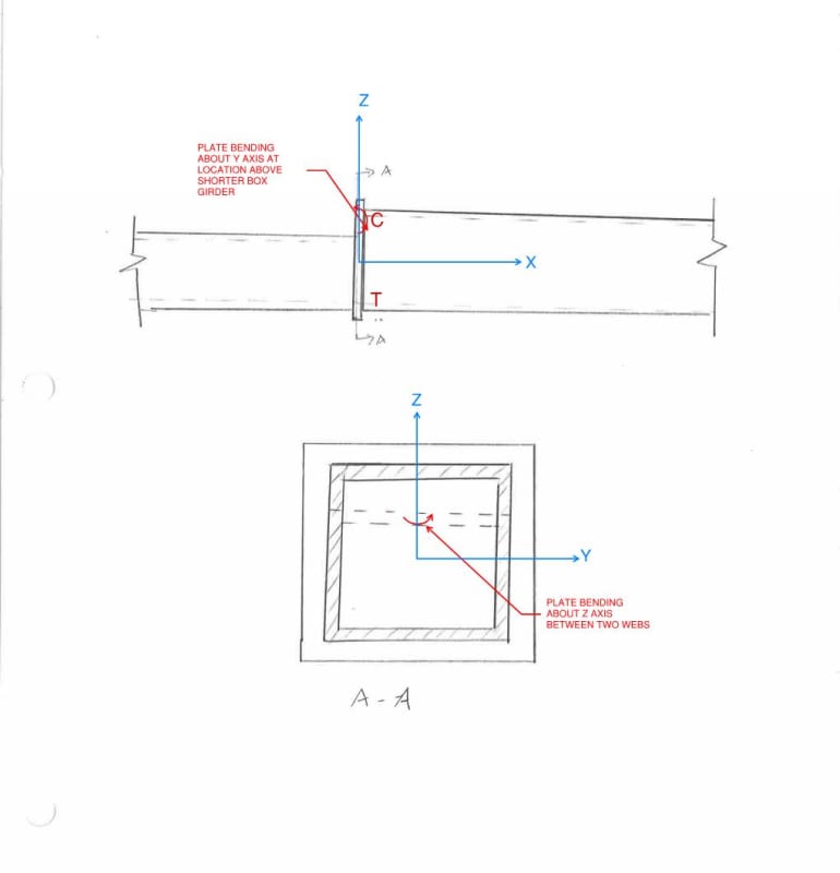
I am designing a steel transfer structure which includes box girders. I have a couple of instances where the box girder depth must reduce at a step. I plan to include a stiff plate at this transition, but want to be sure that I have all of my bases covered for the plate bending stresses to be considered here. The beam is in positive bending at the location of the step, and I am thinking about the following:
1. Bending of the plate above the reduced-depth section -- this is difficult for me to really visualize happening, as the two webs would have to bend in plane over the flange of the lower section
2. bending of the plate between the two webs of the full-depth section -- it is difficult for me to imagine this stress being very large; the distance between webs is short and the plate is not stiff relative to the sections themselves.
I've attached an image below to show these conditions I am thinking of:
Stepping_Box_Girder_sncxbz.jpg


Because I am not convinced that either of these conditions could result in significant plate bending, I am wondering if there are additional forces that I am not considering yet.
If anyone has any input or resources that relate to this condition, that would be fantastic.
Thank-you so much!
 
Replies continue below

Recommended for you

Oh... I see. Your transfer column thread panned out gang busters and now you're getting greedy! Kidding of course.

c01_qlcwa6.jpg
 
While it's not a universal, unbreakable truth, a good steel connection principle is to favor moving load through plates taxed axially and in shear rather than via plate bending. Plate bending will usually make for less efficient, and less certain, load transfer.
 
Also, at the tension butt, I'd prefer either full penetration groove welding between the two box section flanges directly or a splice plate. While I don't believe that this is technically a lamellar tearing situation, it's kinda got that feel to it and it makes me uneasy for something as important as this.

c01_mj0z9n.jpg
 
EfFeb:
Again, load magnitudes, dimensions, member sizes and thicknesses, sketch proportions, etc. mean a lot to an experienced engineer’s first impression of your problem. Are you cutting this step into an existing box girder or extending an existing canti. girder, or what? Where do you think the top flg. forces on the left beam (shallower bm.) go? How do they get into the top flg. of the deeper beam? Won’t they actually be concentrated, as very high bearing stresses, right where the lower top flg. meets the web of the deeper beam section, not a practical/reasonable situation? Get rid of the end pl. btwn. the two beam parts, it req’rs. as much welding as other solutions, and high through pl. stresses are not ideal. Maybe design it as an end pl. moment connection, then design and detail accordingly. Otherwise, prep the ends of the two beam parts for CJP groove welds, backer bars, bevels, etc. Put a horiz. pl. into the end of the deeper beam, web to web, and some length to be determined, same thickness and elevation at the lower top flg. Get that lower flg. load into the webs of the deeper member in some meaningful way. Put a .25” closure pl. on the upper end of the deeper beam. If you can hide it, you could cut triangular pieces out of the two upper webs of the deeper member, bend the top flg. down to meet the elev. of the lower top flg. and weld it all back together. Take care of the web to flg. welds, as the compression in the flg. in this detail tends to force (pull) the flg. away from the webs, a significant secondary stress consideration.

 
Thanks to both of you.
I had been hoping to avoid adding an internal horizontal plate at the deeper member, but this seems to be the clearest way to get the force from the top flange of the shallower member into the webs of the deeper member without creating stress concentrations at locations where the webs and flange meet, as dhengr mentioned.
The step is not to be cut into an existing box girder, rather it is a connection between two box girders of different depths.
dhengr, you mention the secondary stress from caused when compression in the flange pulls the flange away from the webs. Are you mentioning this as a general consideration for the box girder welding, or as something that is more critical at this connection?
Thanks again for all of the feedback
 
efFeb said:
I had been hoping to avoid adding an internal horizontal plate at the deeper member

I suppose that it might make more sense to slot the horizontal stiffener into the bigger box rather than having it be truly internal.
 
EfFeb:
I’ve designed and fabed box girders that you could walk around in, and I’ve used HSS sections too. Box girders usually imply something larger than an HSS. Many of these you can get into, a foot or so on the ends, to do some fillet welds btwn. a pl. and the box side pls., your sketch isn’t clear on this. Again, this is why dimensions and sketch proportions are important info. in your description of the problem. Are the pl. thicknesses and the box widths the same on the two different boxes you are dealing with? This is another area which will cause detailing and design problems if not squared away up front. In butting these two box girders end to end, do you end up with a longer span length, and can the smaller box handle this? When you set these up for welding you may want to actually build a little camber into the new member, and pay attention to how welding will move that joint and the members around.

My comment about flgs. pulling away from webs pertained to my suggestion of a sloped transition flg. When a sloped flg. changes direction, slope to horiz., slope to new slope or curved for example, there can be a fairly significant force component perpendicular to the flg. pl. At these transitions, you are dealing with the normal shear flow flg. to web, and this perpendicular force component combined. A tension flg. tends to pull the flg. into the webs, while a compression flg. tends to push the flg. away from the webs. We used to deal with this by having a groove bevel ground into the webs some inches on either side of the transition curve. Then, the welder filled the groove and then did the normal fillets over that.
 
I normally do something like this and weld in an insert cut from one of the parent boxes, assuming the webs can deliver sufficient resultant force to prevent buckling.
2020-02-21_12_15_52-1676_001.pdf_-_Adobe_Acrobat_Pro_rnuakm.jpg
 
I would suggest putting a tapered transition section. Slope 2 to 1 at a minimum but that is just a gut reaction.
 
I feel that the tapered segment approach is misguided for any seriously loaded situation. The resultant forces shown in RandomTaskkk's sketch will induce unmanageable, transverse plate bending stresses in the top flanges of all three parts unless there are vertical stiffeners installed to turn the flange loads at those locations.
 
Agreed, only a solution for low loads. But we have no idea of OPs loads or section sizes, so perhaps it's viable.
 
Yeah, I make a very similar argument to justify the knuckles of stair stringers.
 
I would have to disagree on the tapered section. I assume the side walls and bottom stay in line while the top would slope down to the new elevation. As I am imaging the section the result is a gradual change in section modulus and sloping of the neutral axis from one side to the other.

I have not done any calculations so I could be missing something but I don't understand where the transverse bending loads come from. As I see the transition you just have a gradual change in section modulus and NA location along the length. I am assuming also all side maintain the same plate thickness and are flush on both sides.

IMG_20200221_174014_fgfbht.jpg
 
@ldeem: is it correct to assume that your sketch does not have internal stiffeners at the horizontal lines?
 
I struggle to find the perfect, convincing sketch for this that doesn't demand more of my isometric drawing abilities than I can muster.

c01_fpm91h.jpg
 
Kook, I understand what you are sketching and it is a very good point. I am thinking more 2D than what you are sketching but I do recognize the out of plane forces due to the angle - I just didn't consider them to be enough to create a problem for plate bending. My initial though process was bin to cone transitions, those sometimes have ring stiffeners but bins are typically large spans and thin plates compared to a beam.

I suppose an FEA would answer the question but the complexity of doing that may be too much when there are simpler answers. Maybe if I ever get some down time I'll do one and see what happens. As with most everything the loads and width thickness of the plates would have a huge impact.
 
Great, I was not relishing the thought of more, tedious isometric work.

Without a doubt, tapering does help. At some value of slope it works without issue. The only question is whether or not that's 1:2 or 1:10. For a critical element where one may be attempting to plastify the top flange in flexure. I feel it's closer to the latter. And, more importantly, worthy of real consideration.
 
Status
Not open for further replies.

Part and Inventory Search

Sponsor