Continue to Site

Eng-Tips is the largest engineering community on the Internet

Intelligent Work Forums for Engineering Professionals

  • Congratulations cowski on being selected by the Eng-Tips community for having the most helpful posts in the forums last week. Way to Go!

Detailed design of a burst/rupture disk connection

Status
Not open for further replies.

KevinNZ

Mechanical
Jun 12, 2003
850
Hi

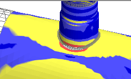
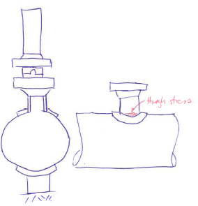
Does anyone a good design approach to the detailed design of a burst/rupture disk connections. As below this is the connection of a short stub to the mainline. The thrust force from the disk puts a large force trough the stub to main connection and around the pipe shoe under the connection.

We have checked the stress with FEA (Nozzpro) and find high stress at the edge of the stub weld. The stub has to be very thick before this stress is under code.

Is there a better detail?

We have seen reinforcing rings welded from the stub around to the pipe shoe.

Thanks.
disk_iavpiq.png
 
Replies continue below

Recommended for you

What thrust force?

The force from an end cap force as the disc is essentially a fixed end?
Or the thrust from the escaping fluid ( gas? liquid? Steam?). I appreciate there must be a reaction force somewhere to balance the fluid energy / momentum of the fluid escaping, but I can't quite get my head around where that force would appear.

Can't quite see where your forces are that would cause issues with the stub which is more commonly associated with bending moment on the tee.

what sizes, pressure etc are we talking here?
Can't you use a "weldolet" (IRBF)
which "code"?

Remember - More details = better answers
Also: If you get a response it's polite to respond to it.
 
LittleInch

There is downward force from the fluid jetting out the discharge tube. We are OK with working what this force is.

Other example details would be
Disk size DN300
Line size DN900
Design pressure of system 32 bar
Design code B31.1

The piping design code does not provide a method of calculation of stress since the discharge is directly over the pipe shoe and does not produce any bending moment. Piping codes only deal with moments.

Screen shot from FEA below. High stress in the edge of the branch weld.
disk_fkjm3y.png
 
Did you check API RP 520 Part 2.

GDD
Canada
 
A couple of things here to help us.

1) Where is the model applying the force from the jet of fluid?
2) what exactly is this connection? - Your sketch looks like a classic reinforced branch design, but the FEA snap shot looks more like some sort of strange reinforced branch fitting with no reinforcement of the header as per your sketch.
3) I'm struggling to see where the bending force is coming from either on the branch or the header to cause that excess stress.
Any reason you can't use a reducing tee? or a standard "weldolet"

Remember - More details = better answers
Also: If you get a response it's polite to respond to it.
 
Thanks for your responses

API 520 says
The designer is responsible for analyzing the discharge system to determine if the reaction forces and the associated bending moments will cause excessive stresses on any of the components in the system. A method for the design of piping systems to withstand reaction forces from pressure relief devices is given in Appendix II of ASME B31.1. ...consideration in the analysis of the bending moments.​

B31.1 says
The vent pipe anchor and restraint system must be capable of taking the moments caused by these two forces, and also be capable of staining the unbalanced forces in the vertical and horizontal directions
One of the most important considerations related to the mechanical design and analysis of safety valve installation is the identification and calculation of the moments at critical points in the installation.

Standard branch connections shall as a minimum meet the requirements of para. 104.3. It should be noted that branch connections on headers frequently do not have
sufficient reinforcement when used as a connection for a safety valve. It may be necessary to provide additional reinforcing (weld deposit buildup) or special headers that will satisfactorily withstand the reaction moments applied.​

Our FEA shows the forces (without moments) do put high local stress into the piping.

In years past, I bet most installations only looked at bending moments. Do we have to design for moments and forces?


Status
Not open for further replies.

Part and Inventory Search

Sponsor