Continue to Site

Eng-Tips is the largest engineering community on the Internet

Intelligent Work Forums for Engineering Professionals

  • Congratulations waross on being selected by the Eng-Tips community for having the most helpful posts in the forums last week. Way to Go!

Designing a handheld, battery powered device. Need advice on minimizing motor slowing under load. 3

Status
Not open for further replies.

CarbonBasedLifeform

Mechanical
Jul 21, 2017
5
Hi there,

I'm currently designing a handheld, motorized device and I unfortunately don't have the knowledge about circuits/motors to know how to resolve the issue with my first prototype.

A little about the device: I'm powering a 37mm geared and brushed DC motor at <6V by means of four AAA batteries. The circuit is extremely rudimentary: I have the four batteries in series connected to the motor through a switch.

In testing, the device does not offer enough torque (I can stop the shaft with my fingers), nor does it spin quickly enough. Ideally I'd like the device to be able to overpower hand-strength forces (I know, very vague here. I haven't calculated specific torque numbers yet.) Think of something with roughly 50% the size and torque requirements of a palm sander.

My question is: is the lack of torque/speed simply a result of the weak power supply, or is there something I could add to my circuit that would help prevent the motor from slowing/stopping while under load? For some reason a diode comes to mind, but I'm fairly useless when it comes to various electronic components...

Thanks!

 
Replies continue below

Recommended for you

As a gross approximation, think of torque and current being synonymous; if you want more torque, you need more current at a given speed. In your case that means larger batteries capable of storing more energy and releasing it as higher current, or more in parallel to accomplish the same net effect.

At the same time, speed in a simple DC motor is most closely related to voltage. So if you want more speed, you need higher voltage. In your case that is more batteries in series, releasing the same current at a higher voltage.

Gear reductions can change the equation for one, at the expense of the other. So you can attain more torque by increasing the gear ratio, but that will cost you speed. So if you want higher speed feeding a gearbox to get high torque, you must increase the voltage.

The energy you want to exert, i.e. the "work" you want to perform, is a function of power and time. Power in a motor is torque and speed. So if you want more torque and speed, you need more power. Electrical power is a result of voltage and current. So if you need more power, you need more batteries.

Add to this the fact that you want to maintain a particular amount of power output from your device, understand that as you draw energy from a battery, you are decreasing the voltage potential. That's why even though you are seeing that your device has insufficient power, you are simultaneously seeing that power diminish quickly. That's because as soon as you draw 6V power from those batteries, they are immediately no longer putting out 6V. So if you want to maintain a particular power output level with batteries, you must start OUT with more voltage than you need, then regulate it as the batteries are drained. In addition, the current (torque capability) is a function of the total battery storage capacity, typically measures in amp-hours. So batteries in parallel store more amp-hrs.

So bottom line; there is no free lunch. You need more power for longer, ergo more batteries. More in series to overcome the losses as the batteries drain, more in parallel to to provide more current for torque. You could change the equation with a higher gear ratio so that you increase the base speed (series batteries) in exchange for the torque (parallel batteries), which might end up more manageable. But if you don't want the speed to droop as you use the batteries, you need a voltage regulator; i.e. you have 12V available, a 6V motor, and a regulator that only allows 6V to get to the motor, so the battery pack can drop to 50% capacity before you start to notice. that's what's going on inside of your cordless drill; the battery pack is 18V, the drill motor is only 6V or 9V. But if you've ever used one to the point of exhausting the batteries, you've noticed that the speed is dropping fast toward the end.


"You measure the size of the accomplishment by the obstacles you had to overcome to reach your goals" -- Booker T. Washington
 
I have a new question regarding the voltage regulator portion of the circuit.

I've updated the design to run off of 2 li-ion 14500 cells(so 7.4V nominally). The plan is to regulate that voltage down to 3.3V and run this motor.

I bought two of these voltage regulators, and I realize now that these won't be a simple plug-and-play solution, since the motor will likely draw far more current than those can handle.

My question is this: can someone point me toward the components I need to down-regulate the battery voltage (7.4V) to ~3V in order to run my motor?

I know li-ion batteries bring complications, but let's ignore that for the time being. This is still in rough prototyping phase.
 
Not sure where to even start on this..

1) Why are buying a 6V motor then trying to run it on 3.3V?

2) You never regulate voltage into a motor as it's an enormous waste of power.

3) You power a motor like that directly off the batteries. It matters not that the batteries are a volt and a half higher than the motor. Thru PWM you control the average voltage and current assailing the motor. Look up "PWM speed controller".
Example: [URL unfurl="true"]http://www.electronics-tutorials.ws/blog/pulse-width-modulation.html[/url]

4) Your lack of this fundamental knowledge (nothing wrong with that) leads me to believe you also lack the necessary knowledge about using potentially dangerous Li-Ion batteries. I encourage you to study them and find a Li-Ion charger to safely recharge them and use only cells with built-in protection.
Examples:
[URL unfurl="true"]http://www.batteryuniversity.com/learn/article/how_to_prolong_lithium_based_batteries[/url]
[link 2bfly.com/knowledgebase/battery-chargers/lithium-dos-and-donts/]2bfly.com/knowledgebase/battery-chargers/lithium-dos-and-donts/[/url]

5) Typically this would all be done with a microcontroller, an H-Bridge, and software. The micro would generate the PWM. The H-Bridge would provide the amplification to the motor. The micro would also manage battery charging and fuel-gauging. The software would be the rules running it all and provide the human interface.

Keith Cress
kcress -
 
Thanks for the response, I realize I'm extremely out of my depth with electronics here, hence why I'm asking for help. I'm currently only interested in making proof-of-concept prototype. If this project goes beyond an initial product pitch, I'll be hiring a proper electrical engineer to handle the nuances of li-ion power, etc.

With that said, I'll do my best to answer your questions and ask a few of my own to clarify.

1)I'm buying a 6V motor because finding 3V motors with the dimensional and mechanical specifications I need is proving challenging. Is running a 6V rated motor at 3V somehow bad? I noticed on Sparkfun's website that they list a range of voltages on some motors. Is there something special about those motors to be able to take a range of input voltages?

In jraef's post, he mentions that cordless drills are often powered with a battery whose voltage is higher than what the motor uses (e.g. 18V battery, 6- or 9-volt motor). Presumably this means the raw battery voltage is stepped down to something the motor can use. Is this correct? Or is the trigger effectively using PWM to "regulate" the voltage?

My main reason for following jraef's advice is I want this device to maintain decent power even while under load. Preferably I'd like the power not to fade gradually as the battery charge is used. I'm essentially looking for similar usage characteristics as a modern cordless drill, just with less power.

2) Makes sense that regulating voltage into a motor would be wasteful. Perhaps it's better to simply find a motor/gearbox combo that offers the right characteristics?

3) This device does not need to be variable-speed. I only have a simple on/off switch.

4) I've done a significant amount of reading on li-ion batteries and I'm fully aware of their dangers. For this prototype I intend to use protected 14500 cells with a li-ion wall-charger. I'll be removing the batteries to charge them. Once the concept is proven, we'll be hiring an electrical engineer to handle the onboard charge/discharge protection, etc.

5) Does using Li-ion batteries necessitate using a microcontroller + PWM in a device whose function is no more complicated than a battery, an on/off switch, and a motor? Think of, say, an electric toothbrush.

Thanks!
 
DC motors aren't 'voltage' driven. They are current driven. What the voltage rating usually refers to is the back-emf the motor produces at its rated RPM. Typically it's best if that is the same as the supply voltage so the motor won't burn up under no-load conditions, but it's only best if there will be a no-load condition. If one tries to put a higher voltage on it the current will continue to go up, but the RPM won't because the motor will be magnetically saturated and produce no more torque.

If you run a 6 volt motor with 3 volts it will take more current, possibly more than the windings can handle and it will damage the insulation from overheating, short out, and become not a motor. The ranges at Sparkfun are those between which the motor can move with no load (low current) and maximum back-emf. They should refer to the current limits of the motor, but they are selling to amateurs who can find batteries more easily than current controllers.

Microcontrollers that can handle these tasks are now less than 50 cents. Your simple function isn't simple.

If you want less power than a cordless drill, look at a cordless screwdriver.
 
3DD makes a good point about a cordless screwdriver. You can probably get one for $40 that has the battery/charger/speed control/motor/gearbox. Hack them all into the form-factor you want.

Glad you've given Li-Ion an in-depth look.

You can also use the motor you have and the batteries you have with any of thousands of PWM controllers available for cheap.

For-instance at DealExxtreme I put in "motor speed controller" and got 180 speed controllers.
[URL unfurl="true"]http://www.dx.com/s/motor+speed+controller?cateId=0&cateName=All%20Categories[/url]

The first one is:
[URL unfurl="true"]http://www.dx.com/p/pwm-dc-6v-90v-15a-motor-speed-control-switch-448980#.WXp9ZoTysz0[/url]

And looks like it would serve you well. You don't want variable speed? Fine set the knob where you want it and don't touch it again.


Answers:
In jraef's post, he mentions that cordless drills are often powered with a battery whose voltage is higher than what the motor uses (e.g. 18V battery, 6- or 9-volt motor). Presumably this means the raw battery voltage is stepped down to something the motor can use. Is this correct? Or is the trigger effectively using PWM to "regulate" the voltage?

1) Yes the PWM is the voltage regulator in this case. Actually as 3DD sez current regulator. A motor averages what it sees.

2) Makes sense that regulating voltage into a motor would be wasteful. Perhaps it's better to simply find a motor/gearbox combo that offers the right characteristics?

2) Always. That said, small motors are often sent odd voltages no one designed them specifically for. It doesn't actually matter much usually as it's ALL about temperature. If you grossly drive them briefly they don't typically care as long as the thermal time constant keeps them from exceeding their insulation temperature rating.

3) This device does not need to be variable-speed. I only have a simple on/off switch.

3) Doesn't mean you can't use a PWM driver to tailor the power/speed/torque.

4) I've done a significant amount of reading on li-ion batteries and I'm fully aware of their dangers. For this prototype I intend to use protected 14500 cells with a li-ion wall-charger. I'll be removing the batteries to charge them. Once the concept is proven, we'll be hiring an electrical engineer to handle the onboard charge/discharge protection, etc.

4) Good good good.

5) Does using Li-ion batteries necessitate using a microcontroller + PWM in a device whose function is no more complicated than a battery, an on/off switch, and a motor? Think of, say, an electric toothbrush.

5) Certainly not. Just that what I mentioned above makes processors the most cost effective, flexible, and dependable method (in a formal product).

Keith Cress
kcress -
 
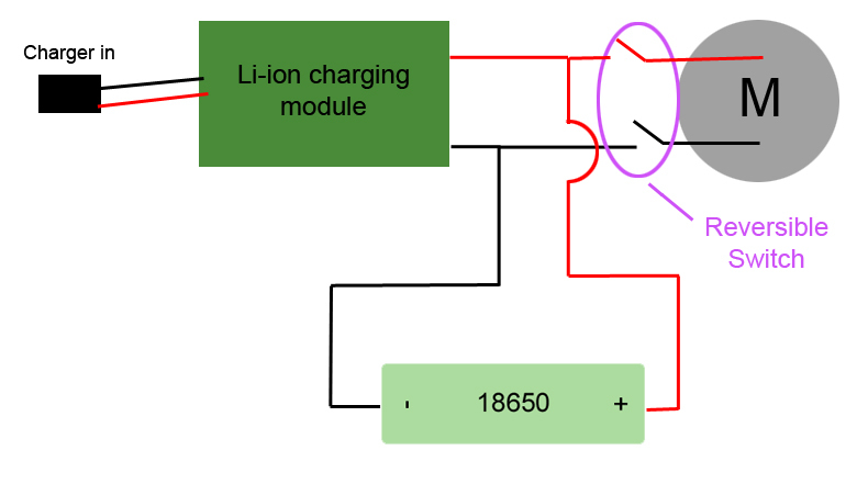
Awesome, thanks so much for the help. A power screwdriver arrived on my doorstep today in fact. After disassembling it, I drew up a diagram with the major components for you to reference. This is a Black & Decker LI2000, if anyone's interested.

ElectricScrewdriverSchematic_mvaak2.jpg


Aside from a li-ion charge protection module, the circuit consists of a single 18650 cell hardwired directly to a 3.6v motor through a reversible switch (for forward/backward screwdriving). The motor output is sent through an 8:1 planetary reduction gearbox. The screwdriver offers exactly the sort of use characteristics I want, minus the fact that the motor/gearbox/battery are too large for the device I'm designing.

Considering my first circuit was nearly identical, it would seem that the solution lies with some combination of the power source, motor, and gearbox. Can someone confirm/refute my thinking:

My first guess is my original power source lacked sufficient capacity or discharge capability. My first prototype consisted of four AAAs in series giving 6V, but that's only 750mAh when fully charged. I would bet a pretty penny that the 18650 has significantly better capacity and/or a higher discharge rate. I had that connected to a 6V motor that claims 260rpm through a gearbox. I'm not positive what the gear reduction on that is, but I think it's in the 45:1 range.

Another guess would be that the my original motor was too much of a high-speed/low-torque sort of number. Though one would think that the 45:1 gearbox would take care of that issue. I'm putting my money on my first guess.

Let's assume that I'm stuck with a 6V motor (3V gearbox motors of sufficient size are hard to find). For my quick 'n dirty prototype, does it sound reasonable to put two 14500 li-ion cells of decent capacity (1200mAh, for example) with built-in protection in series and simply run them through the switch and into the motor? That should be reasonably safe for something that only has to work for a few minutes at a product pitch, shouldn't it?
 
A quick tutorial on brushed DC motors.
Most small brushed DC motors have a permanent magnet field and that is what this tutorial addresses.
First, lets look at generation:
A brushed Permanent Magnet motor will act as a generator whenever it is turning.
The voltage will be closely proportional to the speed. For simplicity we will assume the voltage is directly proportional to the speed. The errors will be quite small.
Let's state that our example motor generates 10 Volts when it is turning at 1000 RPM.
Now let's look at motor action.
Now we apply 10 Volts to the motor. The motor runs at 950 RPM with 10 Volts applied.
But because it is turning it is also generating. At 950 RPM it will generate 9.5 Volts.
When we are discussing motors the generated voltage is called the back EMF.
With 10 Volts applied and a back EMF of 9.5 Volts we will have 10V - 9.5V or 0.5 volts to drive the current through the resistance of the armature circuit.
Now start to load up the motor. The motor will slow down.
Let's load it up until the speed drops to 900 RPM. Now the back EMF is 9 Volts and we have 1 Volt driving the current through the armature circuit.
At 800 RPM the back EMF will be 8 Volts and we will have 2 Volts driving the current.
Now this is a motor connected directly to a stable voltage source with no speed controls whatever. This illustrates the basic action of the motor and the effect of slowing speed on the back EMF and on the current.

Speed regulation:
The lower the resistance of the armature circuit the higher the no load speed of the motor and the better the speed regulation.
Let's change the motor specs. Now our motor runs at 990 RPM with no load. The back EMF is now 9.9 Volts.
The load that originally slowed the motor to 800 RPM will now slow the motor to about 960 RPM.
The lower the resistance of the armature circuit, the less the motor speed will drop under a given load.

Voltage:
Small brushed PM motors are quite forgiving of voltage. Mostly.
Take our original motor rated at 10 Volts and 1000 RPM. Apply 7.5 Volts and it will turn at 750 RPM.
Apply 15 Volts and it will turn at 1500 RPM.
What is the downside of over voltage?

Starting current.
When the motor is started the back EMF is zero and the full applied voltage acts to drive current through the armature circuit.
150% applied voltage means 150% starting current and 150% starting torque. Sometimes an issue, sometimes not an issue.

Speed.
If the speed is increased too much, centrifugal force may throw the armature apart.

Load.
If a motor is being evaluated for a given load at a given increased speed the load should not be an issue.
If a motor is coupled to an existing load and the speed is increased, load on the motor may increase dramatically. This is especially true of fans and centrifugal pumps.

A suggestion.
Decide how much you want to discharge your batteries.
As an example, you may want to limit 7.4 Volt batteries to 6.4 Volts.
Use a 6 Volt motor and you will have 0.4 Volts safety margin. PWM your battery voltage to 6 Volts.
This is an example for illustration. Keith is better able than I to suggest recommended voltages.
But, in the event that you can't make a 6 volt motor work, don't despair, plan on running your 6 Volt motor with 5 Volts and select the appropriate gear ratio to get the wanted final speed.
Depending on your load characteristics you may not need a speed regulation circuit.


Bill
--------------------
"Why not the best?"
Jimmy Carter
 
Status
Not open for further replies.

Part and Inventory Search

Sponsor