Continue to Site

Eng-Tips is the largest engineering community on the Internet

Intelligent Work Forums for Engineering Professionals

  • Congratulations 3DDave on being selected by the Eng-Tips community for having the most helpful posts in the forums last week. Way to Go!

Designing a cam

RoarkS

Mechanical
Jul 10, 2009
271
Hey folks,
Would like an idiot check.
I'm working on designing the camshaft for a small 4 stroke generator engine that will run at 5000 rpm. I've spent about 3 weeks total on cam design thus far and am having an absolute panic attack. lol

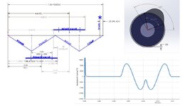
the cam has a base circle of Ø1.125 and a roller follower Ø.5

I started with cycloid, then modified trap, 3-4-5, then higher order... started messing with Cubic Bézier splines... and more less ended back up with a 3-4-5.

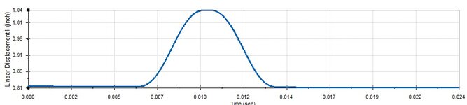
Anyway... I've been trying to keep things under 100g of acceleration and finally made it.

Ended up with a 3-4-5 that has a 100deg rise, and 100 deg fall no dwell. The actual equation says I should be getting about 79g but the simulation came back with a peak of 96.7g. I think that has everything to do with roller contact angle/pressure angle...

That said I was like oh... I'll just plot the roller center then cut out as it rotates to get the lifter to do what I want... omg. that's not possible... at least my simple brain can deal with it.

Anywhoo... I'm already at 200 degrees seat to seat on the cam. It's boxer engine, so no offsetting the cam bore I think this is it.

Is there anything else I can do?
 
Replies continue below

Recommended for you

Along with the mechanics for 5000 rpm, you should be looking at the fluid dynamics...
Do you have a calibrated engine model telling you what volumetric efficiency you will be getting with a given cam profile, valve diameter, and port flow coefficient set? ASSuming you have a power target and aren't willing to just take what you get.
 
200 degrees seat-to-seat duration sounds shy. Intake valve opening will probably be 10 or 15 degrees BTDC and intake valve closing will probably be at least 30 degrees ABDC and probably more, unless there's something going on that the rest of us don't know about. Lobe center at 100 - 105 degrees ATDC is in the plausible range. That would give 110 - 120 degrees to open and the same to close (if you use a symmetrical lobe) which would help cut down your acceleration. Obviously the right way to pin the cam timing down would be with a proper simulation.

Nominal valve event timings are often given at 1mm or 0.050" lift depending on whether you live in a metric or imperial world - this will differ quite a bit from the seat-to-seat durations.

Complexities ... If you are dealing with manually-adjusted mechanical solid lifters (no hydraulic automatic lash mechanisms) you are going to need a lead-in and lead-out ramp at the beginning and end of the lift profile, to allow the valve clearance at the maximum clearance-specification limit to be taken up consistently before lifting the valve off its seat and to set it down against the seat in a consistent manner. Not an expert but I suspect these will be linear motion profiles, which also means your cam-lobe profile needs to start from a non-zero slope (the lead-in slope) and end in another one.
 
LouScannon: I'm doing a lot of ASSuming. lol... but I'm trying to be very conservative on the assumptions. I'm shooting for 22hp ISA sea level. Done a lot of comparative stuff. I don't have any good fluid dynamics but I'm essentially copying a well known design for head and port geometry. I wouldn't be surprised if I end up closer to 30hp. I just got started with openfoam last week... but there's a steep learning curve there.

BrianPetersen: Really... I was getting scared 200 was too much. I've not done something designed to live at this speed before but I guess. 120 degrees ought to drop it down A LOT more. (yes symmetrical lobe). I've got a pretty good dynamics simulation going right now and feel pretty good about things... but certainly not fluids... just a bunch of hand calcs for combustion speed and so on.

love child of metric stock parts, and inch design... lol. I had read about that .050" thing a long time ago thanks for reminding me that certainly makes me feel better about the 120 degree idea. I'll math it out tomorrow and run the simulation. probably gets me down into the 60-70 g calculated... probably high 70's in the dynamics sim.

Yeah going with solid lifters.... ugh that sounds gross. The 3-4-5 is VERY shallow on it's approach... I think it will be fine? :/
 
Okay. I'm freaking out a little here...
cam lift is 100 degrees on the cam. that means 200 degrees lift to lift on the cam. that's 400 degrees on crank. I'm mapping it out and that seems impossible.

What's considered an acceptable G load?
 
Last edited:
Maybe to help us visualize, you could post your valve lift curves, dimensioned and indexed to TDC, but to scale is optional.
 
Okay. I'm freaking out a little here...
cam lift is 100 degrees on the cam. that means 200 degrees lift to lift on the cam. that's 400 degrees on crank. I'm mapping it out and that seems impossible.

What's considered an acceptable G load?
Correct.
Brian is using crank degrees which is usual. So his suggestion is 220 - 240 crank degrees ie 110 - 120 cam degrees.
 
What's considered an acceptable G load?

Hmmm. I spin my Yamaha R3 roadrace bike to 13 000 rpm pretty regularly. (DOHC 4-valve-per cylinder, 2-cylinder 321cc, nothing particularly high-tech, valvetrain uses direct-actuated buckets, with shims between each valve stem and bucket for setting clearances.) I'd estimate valve lift to be 10mm, and total duration to be probably 260 degrees but both of these are ruff estimates because I haven't the engine apart in front of me at the minute. Just to get an order-of-magnitude guesstimate ... If I ruff-estimate valve opening to be uniform acceleration to half of valve lift over a quarter of the duration (accelerate open, the decelerate to full lift, then the reverse, hence where that's coming from) then that's uniform acceleration to 5mm distance in 65 crank degrees with one revolution happening in 4.6 milliseconds ... so 5mm distance is achieved in 0.833 milliseconds. Uniform acceleration of about 15 000 m/s2 gets in the ballpark. (So 1500 "g") Bear in mind that if you ramp up the acceleration in order to reduce "jerk" - which you will have to, to avoid harmful dynamics - then it must ramp up to a higher value. 2000 "g" perhaps?

Plausibility check. Head of each valve is about 25mm diameter and perhaps 3mm thick, and the stem is 4mm diameter and about 120mm long, so the mass of each valve would be about 25 grams. Don't know about the springs, I'd estimate about the same. Add another 15 grams for the retainer, keepers, shim, and bucket. So 60 grams, 0.060 kg (I think this is a high estimate, I may be overestimating the thickness of the head of the valve, and the springs are only partially reciprocating mass). Means the spring would have to provide 1200 N of force over the nose of the cam lobe. I think that's high, but it isn't orders-of-magnitude high, and you have to consider the following ...

Acceleration off the seat, and setting it back down on the seat, isn't limited by valve spring force. Acceleration over the nose of the cam lobe, is. For fluid dynamic purposes, you want to snap the valve open quick and let it "coast" over the nose of the cam lobe and then set it down quick ... so the higher accelerations are the ones not limited by the valve spring, are also the places where you WANT it to have higher acceleration. Snapping the valve off the seat and setting it down against the seat quickly (high acceleration) would allow gentler acceleration over the nose of the cam where it's limited by the force of the valve spring.

If the engine is an interference design, you had better consider piston-to-valve clearance during the valve-overlap period, too.
 
That's what I figured... I started with a 140 deg cam, 280 deg crank.... cam, but was getting upwards of 250g... felt like that was too much so I started increasing the ramp till I got up to 400deg crank... and yeah that doesn't work. lol. Person I was talking to was definitely talking in crank angle while I was working in cam angles.

is 280 crank too much or do I need to back it down more?
 
@BrianPetersen- Yeah that's what I've been saying in the back of my head... I know what sport bikes run up to. I'm running pushrods, so I ratioed my arm to get the load on the rod down. I just feel like I'm a little chicken and the egg situation... as I'm trying to size the springs, which then drives valve length. I guess I should be happy I'm only seeing 275g. lol. The 3-4-5 is okay with jerk... the higher orders handled jerk better but acceleration was a lot higher. Software I was running is basically telling me the springs are no risk of float at at the moment... so I went after acceleration. IDK. This is my first rodeo going this deep.
 
Seat-to-seat timing, it's possible. (Open 35 BTDC, close 65 ABDC, for example, would get you there.) Give us the corresponding event timings at 1mm lift. With proper ramping-up of acceleration to keep "jerk" finite, it'll take a fair number of crank degrees to get from the seat to 1mm lift.

edit: 280 degrees total duration is probably on the aggressive side for what you are expecting this engine to do. Loads of people have learned the hard way that it's better to make a mistake on the side of shorter duration than long. One way starts nice, idles nice, pulls off the bottom nice, tails off at high revs but generally runs "nice". The other way doesn't have enough static compression to start nice, experiences too much flow-reversion during valve overlap to idle nice, if you are using a carburetor it's hard to tune, is lazy to pull away from a stop even if you get the carb jetting to work, and whether it actually makes any more power on top is contingent upon the rest of the intake system delivering what the cam is asking for ...
 
Last edited:
Well... that's the beauty of it. I'm making it up as I go! lol.
Big company, small department, very lean on resources. Have to do our best to get the prototype to give us good data/hopefully be good enough.

Have a look... tear it apart.

EDIT: I guess I should explain it...
Top left is my timing layout
  • I have degrees in inches 7.2" = 720°
  • ICL intake center line.
  • ECL exhaust center line
Top right is the cam profile 3-4-5 poly
  • 60deg lift, and fall.
  • 120deg seat to seat cam. 240 degrees crank.
  • rocker ratio puts .050 at .033... so at .033 that gives me 80° cam, and 160° crank.
bottom right: accel plot lifter direction with 1/2" roller going over the cam.
 

Attachments

  • as of 61125.jpg
    as of 61125.jpg
    109.3 KB · Views: 12
Last edited:
Its an interesting exercise and its great if that is the reason you are doing this. OTOH if you are designing this yourself because you think it is the best way forward, you need a reality check. The sensible route is to talk to a cam specialist and find a stock profile that can be adapted to your needs. At the very least, find a stock profile with the required duration and scale the lift to match your requirement.

Back to the DIY. Brian's post at 10:38 pm tells you a lot but importantly - your 100g acceleration target is an order of magnitude low.
 
Any chance of putting valve or cam lift in a plot like the top right? I think that's the format we engine types are most used to and able to evaluate.
 
Gruntguru... I hear ya... you're preaching to the choir sir. I reached out to few places... haven't heard back from anyone. soon as I say aircraft and FAA they can't hang up fast enough.... but hey... math is math.... looks right. I've got about a month left before design freeze and we start cutting parts. YOLO.

If that's true, I'm VERY confident with the acceleration forces. that plot is actual lifter dynamics, not just cam data. I'll plug in his 13k rpm just to see what mine comes out with... I bet he's not far off.

EDIT He wasn't far off at all... my cam calculated right at 1984 for peak G load at 7500 cam RPM. That said I also spent a few hours at a engine shop today and the cam they are using is stunningly similar. If anything I bet it's a little wider than mine was. I was genuinely shocked that the .050 lift thing took the event down to 80 deg.

LouScannon:... give me a minute I've got the s plot to match the a. EDIT: see attached plot
 

Attachments

  • as of 61125 s plot.jpg
    as of 61125 s plot.jpg
    47.9 KB · Views: 1
Last edited:

Part and Inventory Search

Sponsor