CivilSigma
Structural
Hello,
I'm studying steel seismic design from the textbook: Seismic and Wind Forces: Structural Design Examples, 5th Edition.
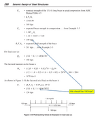
I am on Example 3-3 which illustrates the seismic design forces on a beam in a chevron braced frame.
Per AISC 341 Section F2.3, we need to check the beam for a) Expected tensile brace force + Expected compressive brace force and b) Expected tensile brace force + 0.3*Expected compressive brace force. Section F2.3 tells you how to calculate these forces.
However, in the example on page 288, the author is using the true nominal brace capacity in compression to design the beam. Please see the below screenshot. I disagree with this. Do you agree with me or am I missing something?
Thank you,

