OK, Got it. You are working with a software program and not trying to build an actual motor.
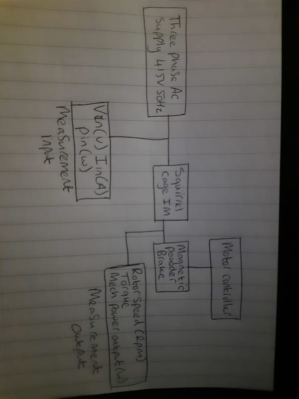
It seems as if you may be trying to design from scratch a complete variable frequency drive system.
A couple of pointers:
Three phase induction motors are plentiful, Off-the-shelf.
Take a look at the Cowern papers for a very good introduction to many aspects and characteristics of induction motors.
Cowern Papers
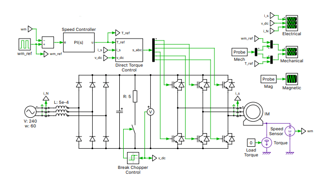
The electronic portion of your drawing is normally combined into one device called a Variable Frequency Drive.
Search this forum for a lot of information on VFDs.
A couple of tips:
An induction motor takes reactive current to establish the rotating magnetic field.
This reactive current is 90 degrees out of phase with the real or load current, and changes slightly under load.
A Watt-meter will show the sum of the load plus the losses, but while not perfectly linear with loading due to the losses, a current value derived from the Wattage will be a much more accurate indication of loading then an Ampere reading.
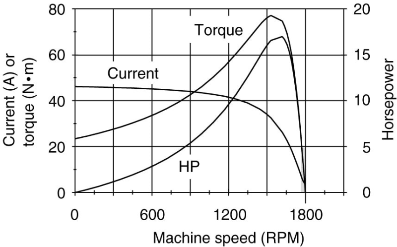
Torque curves.
There are many published torque curves for several designs of standard induction motors.
Almost all of the curves that you will find are for Direct On Line starting.
When using VFDs, the motor is operated in the last 100 RPM of the curves.
That is from the peak of the torque curve to100% speed.
The difference between the synchronous speed and the actual speed is called the slip-speed.
The difference between the applied frequency and the frequency corresponding to the actual frequency is called the slip-frequency.
The slip frequency is the frequency that the rotor sees.
Start with a typical torque curve that is labeled across the bottom in motor RPM. eg: (0-1800 RPM)
reverse the numbers so that 1800 RPM is at the left and 0 RPM is at full speed.
This is now your slip RPM.
This may now be used with good accuracy for any applied frequency.
If the slip speed is 40 RPM, the slip speed at full torque will be 40 RPM slip at any applied frequency within reason.
Another thing that you should be aware of is saturation.
As the applied voltage is increased, the magnetic field increases until magnetic saturation is reached.
If the applied voltage is increased further, the current will increase rapidly and the motor will burn out, possibly in minutes.
But the iron core inductive reactance that limits the current when not saturated is frequency dependent.
If you double the frequency you may also double the voltage without saturating. (Subject to suitable insulation.)
We use a number called the Volts per Hertz ratio.
For your example, 240 Volts and 60 Hertz, the V/Hz ratio is 240V/60Hz or 4 Volts per Hertz.
This is one of the things that a VFD does; It used Pulse-Width-Modulation to reduce the effective applied voltage to match the applied frequency.
This is a simplification.It is capable of a lot more.
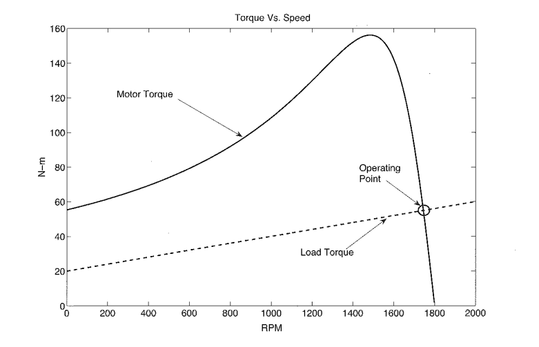
Torque: You don't control the torque. The load demands torque and the motor meets tha demands as long as the demnds are within the motor capability.
Good luck.
(It's late and I don't have time to proof read. If i have made silly mistakes, let me know and I will make corrections.)
Bill
--------------------
Ohm's law
Not just a good idea;
It's the LAW!