Navigation
Install the app
How to install the app on iOS
Follow along with the video below to see how to install our site as a web app on your home screen.
Note: This feature may not be available in some browsers.
More options
Style variation
-
Congratulations cowski on being selected by the Eng-Tips community for having the most helpful posts in the forums last week. Way to Go!
You are using an out of date browser. It may not display this or other websites correctly.
You should upgrade or use an alternative browser.
You should upgrade or use an alternative browser.
Degree of indeterminacy 4
- Thread starter SKJ25POL
- Start date
- Status
- Not open for further replies.
r13,
The support condition at N4 appears different than N1 on the RISA output, yet you are intending a pin at both nodes. Is it possible that RISA is interpreting your input as a roller at N4? That would make the first two cases unstable but not the third.

BA
The support condition at N4 appears different than N1 on the RISA output, yet you are intending a pin at both nodes. Is it possible that RISA is interpreting your input as a roller at N4? That would make the first two cases unstable but not the third.

BA
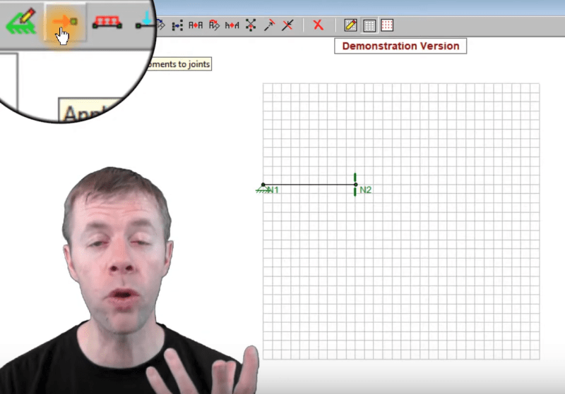
I just took a look at the demo video. The commentator put a hinge at N1 and a roller at N2 and it looks as shown below. That means your program is interpreting Node N4 as a roller, just as hokie66 suggested a few posts back. That is the answer to your dilemma.

BA

BA
-
1
- #63
-
1
- #65
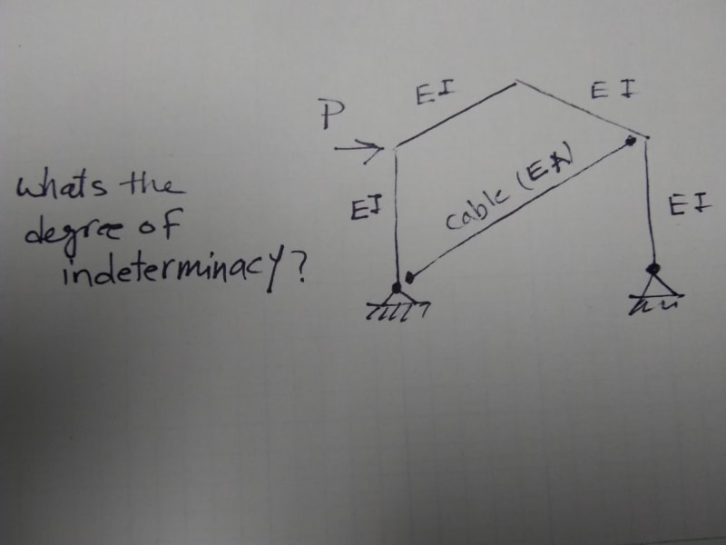
All frames are simply supported, jt#1 pin support, jt#4 roller support (globally determinate). The joint rotational restrains of the brace are released. I believe we all remember that a structure is determinate and stable, if the number of equilibrium equations is equal to the number of knowns; and the structure is indeterminate if the former is less than the later. For my cases, I think the number of equilibrium equations is more than the unknowns.
EI is constant for all members. The circle indicates release of member end rotational restrain. The last model (with joint moment) has no internal release except the brace.
EI is constant for all members. The circle indicates release of member end rotational restrain. The last model (with joint moment) has no internal release except the brace.
-
1
- #67
Settingsun
Structural
R13, if the right-hand column is pinned at the top and on a roller at the bottom, nothing stops it rotating in the plane of the frame (rotating about the top of the column). When you provided a moment connection at the top, you prevented the in-plane rotation so the software stopped reporting the instability.
-
1
- #68
yes, but this is a mathematical "instability" ... that the column would rotate if a load is applied in a direction where there can't be one.
we "know" there are no lateral loads on the RH member 'cause we put a roller at the foundation (no load out means no load in).
we "know" this 'cause we've done it since 2nd year uni.
What I think this is doing is actually very dangerous. the program detects an "instability" and corrects it without really telling the user what it did (much like NASTRAN AUTOSPC).
I don't know how the program defines axially loaded members (like how we want the RH member to behave). Maybe there's an option to define the member as a ROD ?
Giving the RH member zero lateral stiffness would be equivalent to making the foundation a roller joint.
another day in paradise, or is paradise one day closer ?
stevh49,
Thanks. I think you pinned it. node #3 were locked for both cases with warning.
Yes, indeed.
Thanks everybody join in the discussion.
Thanks. I think you pinned it. node #3 were locked for both cases with warning.
rb said:What I think this is doing is actually very dangerous. the program detects an "instability" and corrects it without really telling the user what it did (much like NASTRAN AUTOSPC).
Yes, indeed.
Thanks everybody join in the discussion.
I haven't used the latest version of RISA, but in the previous versions they were pretty clear in their documentation how to handle it, and provide a procedure. First step is to try to determine whether or not you have a modeling error (too many releases in a single joint, for example), and run it again. If that didn't work, then you move on to troubleshooting "LOCKED" joints. Add a boundary condition for the locked condition (if M.y is locked, lock M.y manually with a boundary condition) and re-run the model. If the new boundary condition is resisting moment, then you have a stability problem and the structure needs that added support. If not, then keep on going until you've cleared all your locked joints and you only have reactions at the boundary conditions where you're supposed to see reactions.
All models are found to be stable after the diagonal brace assigned as "truss member (C/T both ways)". For modelling the brace as flexural member with moment release on both ends, there are three stability equations, but only two unknowns, thus causing the internal instability. I hope this finding is valid, and put closure to this exercise. Thanks everybody who has joined this discussion.
That is not the point, r13. You are clouding the issue. Making the diagonal brace capable of taking tension or compression does nothing to stabilize the right hand column, M3. Making the brace a flexural member would work, assuming it is connected to M3 and not M2. Moment release at both ends is obfuscating the issue.
M3 is unstable if it has a hinge on top and a roller on the bottom. Change N4 to a pin and all models will be stable without all the shenanigans with the diagonal brace.
BA
M3 is unstable if it has a hinge on top and a roller on the bottom. Change N4 to a pin and all models will be stable without all the shenanigans with the diagonal brace.
BA
- Status
- Not open for further replies.
Similar threads
- Replies
- 11
- Views
- 2K
- Question
- Replies
- 7
- Views
- 3K
- Question
- Replies
- 3
- Views
- 2K
- Question
- Replies
- 0
- Views
- 3K
- Question
- Replies
- 0
- Views
- 256

