Hello!
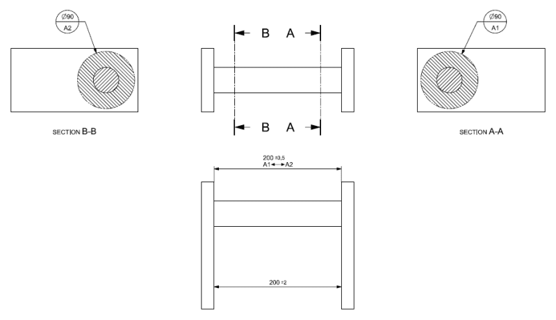
I'm trying to design a part that you could say has two parallell faces interconnected with a shaft. It is important that the finished part has a tighter tolerance around the shaft (e.a 200+-0,5) than the areas further away from the shaft (e.a 200+-2).
How do you specify this on a drawing? I have seen this be done using datum targets, this however feels conflicting with ISO 5459.
Does anyone know if this sort of problem is handled in any ISO standard?
Below is an example of how I have seen it be done with datum targets.
Regards
Daniel S
NX10