Yes, the responses of the three of you are along the lines of what I was thinking:
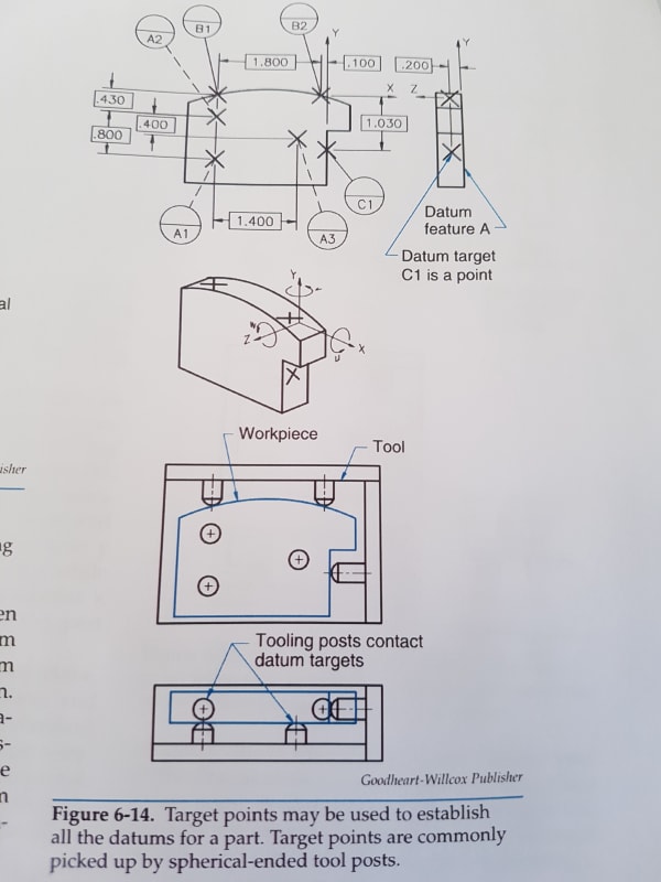
Because of the curved shape of datum feature B, it is different from the situation with a planar datum feature B, to which the description matches.
For this example, I would say:
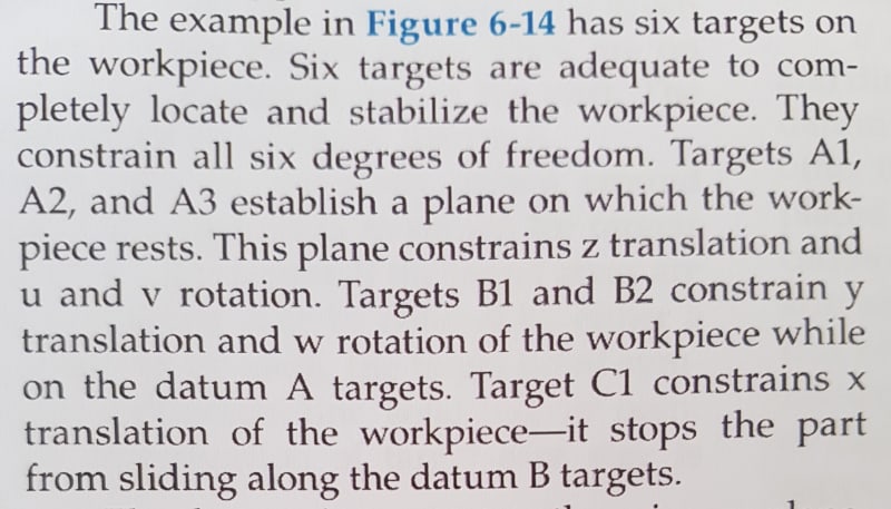
Datum target simulators A constrain Z, u and v (so far the description in the book is correct).
Datum target simulator B constrains Y and X, but not w*.
Because the B simulators constrain X, datum target simulator C does not constrain it. It does constrain w and serves as a clocking datum reference in an |A|B|C| DRF.
* one could make an argument that at the specific location of the DRF as shown, the pins that simulate datum targets B do constrain w, as w is specifically the rotation about Z axis which is at the shown location. But if that was true, an |A|B| DRF would be sufficient to fully define the orientation of any part feature as it would fully constrain 3 rotational DOF. However, when fixtured to A and B simulators, the part can still be manipulated to rotate around the top arc's axis, so any feature with orientation controlled to |A|B| could have different acceptable orientations relative to the third plane of the datum reference frame. Which would not be the case for a planar datum feature B.
Thoughts, objections?


