Continue to Site

Eng-Tips is the largest engineering community on the Internet

Intelligent Work Forums for Engineering Professionals

  • Congratulations waross on being selected by the Eng-Tips community for having the most helpful posts in the forums last week. Way to Go!

Datum targets and DOF constraints

Status
Not open for further replies.

Burunduk

Mechanical
May 2, 2019
2,523
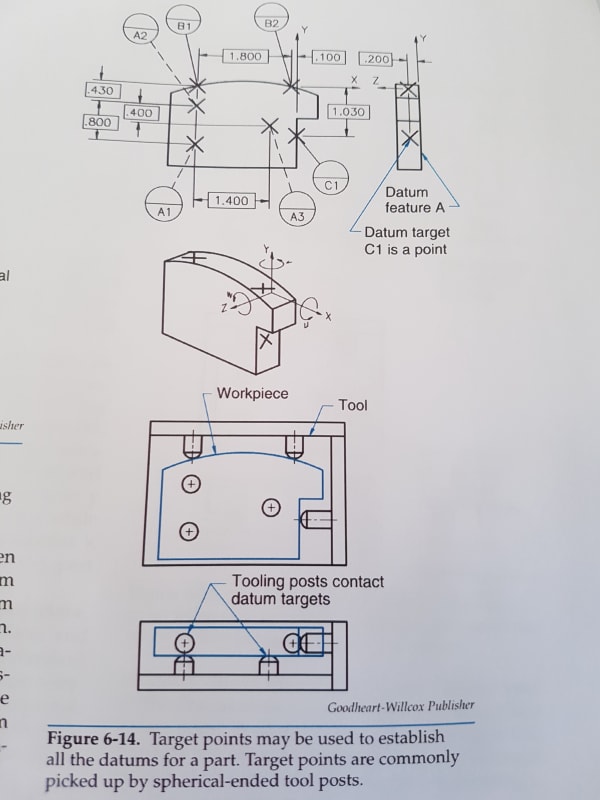
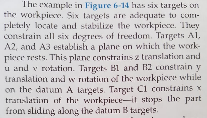
See the attached images from a textbook. Do you consider the DOF constraints description correct? I think there might be a problem there.

20201008_140225_ztw0jw.jpg


20201008_140149_ehjdd1.jpg


The link to the textbook online:is here
Chapter 6 from which the posted images are taken is available as a sample chapter by clicking on the chapter title.
 
Replies continue below

Recommended for you

Are you thinking about something related with datum target B and its capability of arresting its applicable degrees of freedom?

Or maybe x translation is already stopped by B?
 
If that top rounded edge were flat I would say it is correct as described. Because it is rounded it seems to me that the datum targets B1, B2 and C1 work together to constrain (w) rotation and possibly (x) translation as well.
 
I am with chez
Description is lame, but at least 6 targets do constrain 6 degrees of freedom.
Now imagine that part was a sphere...

"For every expert there is an equal and opposite expert"
Arthur C. Clarke Profiles of the future

 
Yes, the responses of the three of you are along the lines of what I was thinking:
Because of the curved shape of datum feature B, it is different from the situation with a planar datum feature B, to which the description matches.

For this example, I would say:

Datum target simulators A constrain Z, u and v (so far the description in the book is correct).

Datum target simulator B constrains Y and X, but not w*.

Because the B simulators constrain X, datum target simulator C does not constrain it. It does constrain w and serves as a clocking datum reference in an |A|B|C| DRF.

* one could make an argument that at the specific location of the DRF as shown, the pins that simulate datum targets B do constrain w, as w is specifically the rotation about Z axis which is at the shown location. But if that was true, an |A|B| DRF would be sufficient to fully define the orientation of any part feature as it would fully constrain 3 rotational DOF. However, when fixtured to A and B simulators, the part can still be manipulated to rotate around the top arc's axis, so any feature with orientation controlled to |A|B| could have different acceptable orientations relative to the third plane of the datum reference frame. Which would not be the case for a planar datum feature B.

Thoughts, objections?
 
A follow-up question:
If you were to specify the location (and orientation + form) of datum feature C (on which target point C is shown) using a profile control, what DRF would you reference? Is it |A|B|, or |A|B|C|, or perhaps |A|B-C|?
chez311 and CH, is my conclusion that you would choose the third option correct?
I would tend towards |A|B| but I would be more confident with it if the radius of the arc (datum feature B) was smaller.

I think that if the book's explanation is accepted regarding the DOF constraints, it would need to be |A|B|C|.
 
Status
Not open for further replies.

Part and Inventory Search

Sponsor