Continue to Site

Eng-Tips is the largest engineering community on the Internet

Intelligent Work Forums for Engineering Professionals

  • Congratulations waross on being selected by the Eng-Tips community for having the most helpful posts in the forums last week. Way to Go!

Datum Structure for Tapered Box

Status
Not open for further replies.

akaf24

Bioengineer
Feb 28, 2019
5
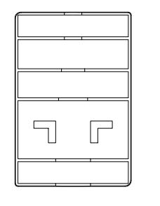
Hey there, I'm still learning proper datum structuring, and I have a simple box that has it's outside wall surfaces tapered. Should I still use these surfaces as a datum? I've attached the drawing PDF, and I am also wondering how to dimension 2 revolved cuts that overlap and can't be seen... Any help is appreciated. Thanks
 
 https://files.engineering.com/getfile.aspx?folder=ea0fc74d-fd9c-4c77-b38c-ce685832b6e5&file=Box.pdf
Replies continue below

Recommended for you

I assume this is a cast or molded part. What standard are you working to?

Datum targets (which can be points,lines and areas) are often utilized on cast/molded surfaces with draft. If you are in the ASME world, Y14.8 might be useful to read through as well as of course the applicable section of Y14.5 on datum targets (section 4.24).

As far as the cuts, if one cannot be seen because it is the same size you can dimension one of them and utilize the "2x" notation, keeping in mind they will be considered part of a pattern (they will also be part of a pattern if they are controlled with separate FCF and the same DRF and material condition/modifiers unless separate requirements is invoked). If you want to dimension/tolerance or put a different control on one of them you OR if they are both hidden behind another feature, you could utilize a separate detail/section view for one or both.
 
Just realized that they could be dimensioned in this view as well as long as the dimensions utilize 180deg opposed points and show the true radius, or a similar section view could be utilized that shows the true radius, or even I believe the true radius could be called out even on a view which does not represent such with the notation "TRUE RADIUS" included like the figure 4-28 in Y14.5 and described in section (1.8.2.3).

box_l8arle.jpg
 
akaf24:

I'm with chez311 on the use of datum targets to control contact locations on the datum feature surfaces.

Regarding the diameters: I could suggest a table to get the dimensions "out" of the views. Label the diameters A,B,C...cross reference them to the sizes in the table.

Certified Sr. GD&T Professional
 
Thanks for the info. Yeah I will do datum targets on the side surfaces with a draft. Unless, if I dimension the holes with a diameter and not radius, could I use the center line of the holes as a datum?
 
If they have at least 180deg opposed points then technically yes they could be a FOS datum - otherwise they would have to be basic and probably controlled with a profile tolerance. In either case (especially the latter), I'm not sure if they would make a reliable datum feature though. At the very least they would probably have to be referenced as a pattern or composite datum feature due to their length to diameter ratio.
 
Status
Not open for further replies.

Part and Inventory Search

Sponsor