Continue to Site

Eng-Tips is the largest engineering community on the Internet

Intelligent Work Forums for Engineering Professionals

  • Congratulations waross on being selected by the Eng-Tips community for having the most helpful posts in the forums last week. Way to Go!

Datum features and relation to Profile of a surface 1

Status
Not open for further replies.

kingofboars

Mechanical
Nov 13, 2019
2
Hello everyone,

we had a discussion the other day that seemed simple but we didn't solve it yet.
In our company the creation of drawings is limited to the minimum regarding effort. We use minimum-dimension TPD, of which I'm not even sure if it's a standard other companies around the globe use it. At least our suppliers know what to do with it.
Result is that new engineers (myself included) are not well-taught how to create proper drawings. If I start thinking about it, I sometimes get a little lost.

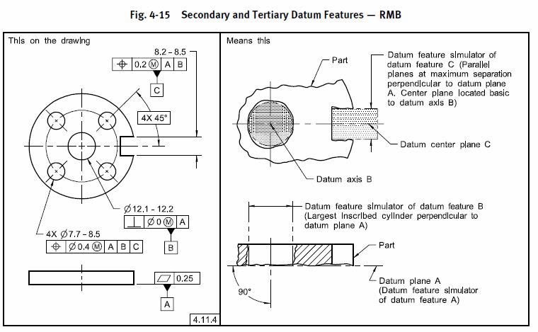
Imagine a arbitrarily shaped metal part (flat back surface that is datum feature A).
The plate has a hole and a slotted hole. The hole is datum feature B, the slotted hole datum feature C.
Now there's a groove in the part in which a tube should fit. It has a control feature: Profile of a surface xx.x A|B|B-C on the cross-sectional area of that groove (since the tube must fit).
My question is: why was B-C used? Could C also suffice?
We think yes, however my colleague came up with a counter-example: the slotted hole now is a hole, so there's two holes in total. One of the holes is datum feature B, the other hole is datum feature C. He says, now you can't use Profile xx.x A|B|C since this doesn't define your profile.

How is that? For me it starts with knowing how it is measured in the first place. I really appreciate your feedback, thanks in advance.
 
Replies continue below

Recommended for you

kingofboars (awesome name by the way, very Game of Thrones),

Is "minimum-dimension TPD" an actual physical standard your company adheres to or just a practice of "apply the minimum amount of dimensions/refinements and cover the rest by all-over/general profile" or something similar? Do your company prints adhere to a drawing/GD&T related standard - say ASME Y14.5 ? If so there are rules laid out in this standard (and related standards such as ISO GPS) as to how to set up a datum reference frame and how many DOF (Degrees of Freedom) each type of datum feature constrains as well. Reading between the lines a bit it seems that either your company does not utilize such a standard, or at least utilizes the concepts contained within standards such as these but relies on tribal knowledge instead of an actual standard to apply the concepts.

To your questions:

why was B-C used? Could C also suffice?

|A|B|C| would be sufficient to constrain all available DOF. Lets assume [x,y] are contained on the plane established by A and [z] is normal to A and [u,v,w] are rotation about and [x,y,z] are translation along axes [x,y,z] respectively. In this case A constrains [z,u,v], B constrains [x,y] and |C| constrains [w]. |A|B|C| could be utilized or |A|B-C| but not |A|B|B-C|. The multiple datum feature designation (ie: B-C) says that two (or more) datum features have the same precedence - repeating a datum reference twice in your DRF (ie: |A|B|B-C| ) is nonsensical and I would say illegal as it says B is both your secondary and tertiary datum feature. B is already established and involved in DOF as your secondary datum feature - there is no need to repeat it.

A similar example from ASME Y14.5-2009

4-15_clrise.jpg


however my colleague came up with a counter-example: the slotted hole now is a hole, so there's two holes in total. One of the holes is datum feature B, the other hole is datum feature C. He says, now you can't use Profile xx.x A|B|C since this doesn't define your profile.

See my above, |A|B|C| is sufficient to constrain all DOF in both cases and does so in the same way I laid out previously. Your true profile and tolerance zone itself (size/shape) is defined regardless of your datum references - the inclusion of datum features defines location/orientation DOF constraint to your DRF (Datum Reference Frame).

A similar example from ASME Y14.5-2009

4-9_thheua.jpg
 
chez311,

first of all, regarding the name: thank you! It's the English translation of what my first name means in my mother tongue (my name is not native).

I'll come back at the standard-TPD set of rules when I know more.

I see a lot of drawings in which people have a plane (datum feature A) and two holes, datum features B and C. Position tolerance for instance, they address to |A|B|B-C|. Before I questioned this I didn't see anybody having a discussion about this way of working.
Do you perhaps have any tips regarding 'basic' books on GD&T?


kingofboars

chez311 said:
The multiple datum feature designation (ie: B-C) says that two (or more) datum features have the same precedence - repeating a datum reference twice in your DRF (ie: |A|B|B-C| ) is nonsensical and I would say illegal as it says B is both your secondary and tertiary datum feature.

Compound datums features define a different datum other than either of the referenced individual datum features (not a matter of precedence)

i.e. two individual co-planar surfaces results in a datum definition other than the individual datum plane that either features would define by themselves ( a plane derived from the individual surfs )

i.e two individual co-axial cylindrical features (internal or external) results in a datum axis definition other than the individual datum that either features would define by themselves ( an axis derived from the individual axis )

for the considered axis of the holes and or hole / slot, from the word description appear to be parallel and do not qualify as a datum derived from compound datum features

it sounds like there is an attempt to orient (clock) the geometric control with the DRF

Workbook examples are good AFTER the standard is read, referenced, basically understand principles even ? . It has always fascinated me over the years that individuals claim to know, understand, "be proficient at", GDT without ever having read and some cases seen the relevant ASME Y14.5 standard

My comment are not meant to criticize anyone.... just expressing my bewilderment

BTW
Cant really do justice for comment without graphic representation


Compound datums features define a different datum other than either of the referenced individual datum features (not a matter of precedence)

The order in which datum references are entered into a FCF determines their order of precedence.

ASME Y14.5-2009 said:
3.4.3 Feature Control Frame Incorporating Two or Three Datum Feature References
Where more than one datum is required, the datum feature reference letters (each followed by a material boundary modifier, where applicable) are entered in separate compartments in the desired order of precedence, from left to right.

A multiple datum feature reference B-C says that B and C have the same precedence. |A|B|C| would suggest the part is brought into contact with A, then the pin for B is expanded, then the pin for C is expanded. |A|B-C| says that instead the simulators for B and C are expanded simultaneously. This is why |A|B|B-C| is nonsensical it would mean that B is both secondary and tertiary and would have to be simulated twice - once for B and a second time for B-C.

for the considered axis of the holes and or hole / slot, from the word description appear to be parallel and do not qualify as a datum derived from compound datum features

I don't know where you got the impression this was the case. |A|B-C| would be a valid DRF, see my above the simulators for B and C would just be expanded simultaneously to form B-C. They could be parallel, perpendicular, or anywhere in between. There is no requirement for multiple datum features to be coplanar or coaxial or anything of the sort. Indeed Y14.5-2009 fig 4-22 shows two stepped/parallel/offset planar surfaces used as a datum feature A-B.
 
Status
Not open for further replies.

Part and Inventory Search

Sponsor