Continue to Site

Eng-Tips is the largest engineering community on the Internet

Intelligent Work Forums for Engineering Professionals

  • Congratulations KootK on being selected by the Eng-Tips community for having the most helpful posts in the forums last week. Way to Go!

DATUM: compound datum composed by two planes and one axis

Status
Not open for further replies.

GOM ATOS _ ZEISS

Automotive
Nov 15, 2016
5
Hello everybody,
I'm Marco, an italian Informatics Industrial Engineer that work on an Optical 3D Scanner and a CMM,
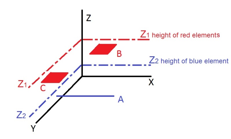
now i have to take a position tolerance (zone 0,4mm), but the primary datum is a compound datum formed by A-B-C
in a Cartesian coordinate system XYZ
A: is an axis in X direction
B and C: are two planes at the same height parallel to Z plane but at different XY coordinate
i don't understand how can define this compound datum with this three elements
if someone can help me it would be really nice.
Thank you in advance and have a NICE DAY!
 
Replies continue below

Recommended for you

Please post a drawing

Certified Sr. GD&T Professional
 
GOM ATOS _ ZEISS,

Your datums must locate your part in six degrees of freedom. By the sound of it, your datums locate in five DOFs, and possibly four. Have you got a picture to show us?

--
JHG
 
SORRY for this poor rappresentation, but for now that is all i can do, I hope that somehow helpful
rappresention_smgfb7.jpg

Tomorrow I will attach the drawing images
drawoh said:
Your datums must locate your part in six degrees of freedom. By the sound of it, your datums locate in five DOFs, and possibly four. Have you got a picture to show us?
Yes, it is, because the position tolerance has also a secondary and tertiary datum that will Clamp the part.
Thanks for participating
 
GOM ATOS _ ZEISS,

Oops. I did not catch that!

Your primary datum is a composite of an axis and two planes. I call up composite datums of two planes or edges, all the time. On a large part with two small, widely separated features, this makes sense. I do not see how an additional axis would work. Three small, widely separated plane faces would normally be called up by datum[ ]targets.

Even a crude sketch on a napkin would help us.

--
JHG
 
______________________
|position|0.4|A-B-C|D|E|
is written in this way,
also i don't understand the additional axis, I do not understand the element that I have to obtain, and how, from the three elements
anyway, tomorrow I will have the drawing.
and thanks for the help given to here
 
Hello again everybody,
unfortunately i can't put on the drawing, but
basically the "problem" is that described above, if someone might reason with me in geometric terms it would be of great help and kindness.
I hope to find many opinions, even for curio and personal completeness.
in the end could also prove incorrect indications of the designer and therefore impossible to define this type of datum.
thank you all in advance and have a nice day
 
Sorry, unless you show the datum features and the relationships between them it is not possible for me to develop a definitive interpretation and respond to your question. Maybe other members can offer assistance.

Certified Sr. GD&T Professional
 
Hi,
mkcski said:
Sorry, unless you show the datum features and the relationships between them it is not possible for me to develop a definitive interpretation and respond to your question. Maybe other members can offer assistance.
first of all thank you for answering,
but, sorry, I did not understand, it is impossible to answer Why does not have enough information or Why with those three elements is impossible to define a datum?
Thank you very much

 
GOM ATOS _ ZEISS,

In order for me to determine the motions restricted by the multiple-feature datums, the relationships between the primary,secondary and tertiary datums must be clearly presented and understood. My time on the forum is gratuitous. My employer allows me to take time to respond to as well ask queston on the forum in a "give and receive" approach. I cannot take the extended time to study your "text" in an attempt to understand your dimensioning schema and gather the needed information or ask more questions. A drawing would "rapidly" present the needed information and allow me to quickly respond.

Certified Sr. GD&T Professional
 
GOM ATOS said:
______________________
|position|0.4|A-B-C|D|E|

I can interpret your feature control frame as per ASME Y14.5. I cannot interpret your actual features without some kind of drawing. I take it you are working to ISO?

--
JHG
 
Status
Not open for further replies.

Part and Inventory Search

Sponsor