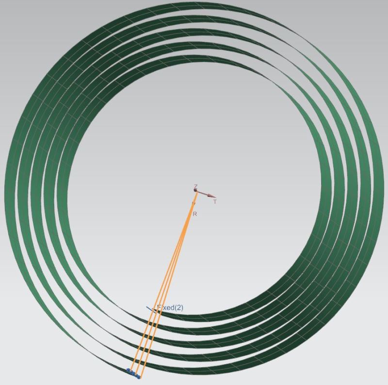
I'm trying to figure out a constraint setup for a clock spring where I pull on the free end and move the spring around as if it were winding.
So I have a cylindrical coordinate system setup where I enforce a rotation displacement using DOF5 (T in degrees) of the cylindrical coordinate system.
But I also what the free end of the spring to remain at a specific distance from the rotation point.
When I attempt to apply a DOF1 (R in mm) the constraint appears to only hold in the direction the R axis is facing at the start of the analysis.
I assumed the constraint would have held as a normal direction around the cylindrical coordinate system as the end of the spring rotated about the center.
Am I mistaken? Or thinking about this incorrectly?
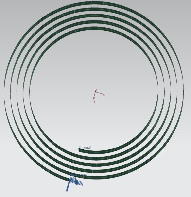