Tek-Tips is the largest IT community on the Internet today!

Members share and learn making Tek-Tips Forums the best source of peer-reviewed technical information on the Internet!

  • Congratulations MintJulep on being selected by the Eng-Tips community for having the most helpful posts in the forums last week. Way to Go!

Cutting a solid for injected casing with a complex parting line

  • Thread starter Thread starter paddlestroke
  • Start date Start date
P

paddlestroke

Guest
Hello,

I am having some difficulities with the following :

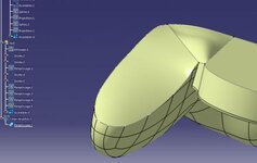
How to cut a solid object in two parts in order to make a plastic injected casing when the cutting line is complex?

Typically for a game controller such as gamecube controller or N64 controller. See for example this picture this N64 controller : http://nfgcontrols.com/grafx/N64-pad-side.jpg


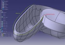
Would you use "cavity and core" tools? Parting line seems adaptated.
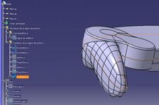
Reflect line give good results on the organic shape. But then I can't figure out what to do to separate the solid in 2 parts, then shell both parts.

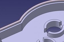
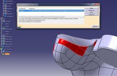
Also is there a way to make borders automatically such that the casing close correctly? Borders such as this picture :
View attachment 1828
Because with this complex parting line it makes it complicated. Can we use the parting line and make a parallel line of it then extrude it?
 

Attachments

  • border.jpg
    border.jpg
    13.1 KB · Views: 1
Please include a picture of the part you're asking about.

Is your goal to have two parts of the casing? (top half and bottom half)

I have not used CATIA's Mold Tooling Design product, so I can't comment on the "cavity and core" methods. Maybe someone else with experience can help? (I did see several videos and tutorials when I searched the internet)
 
Yes I need the 2 parts of the casing.

I succeeded to cut the solid like this :
1 - finishing the parting line into an assembled curve
2 - create new geometrical set
3 - cutting the volume with surface cutting tool.
4 - fill the inner surface by adding some lines
5 - Fill the closed surface into a new solid
6 - Shell with 1mm thickness. But it does not work with more than 1 mm (2 or 3mm) thickness for an unknow reason...

I tried to modify the inner surface by changing the added lines but no luck so far.
I think it's the surface at the reflect line part. I would like to try to add some lines to cut the surface into small pieces but I can't separate the reflect line in small pieces.

Any idea why I can't shell over 1mm thickness?
Error reads in french :
1.La valeur de décalage courante donne une surface localement dégénérée : la pièce ne peut pas être construite.
2.Sommet non reconstruit après décalage, la face
et la courbe incidentes ne se coupant plus.

View attachment 1829
View attachment 1830
View attachment 1831
View attachment 1832
 

Attachments

  • picture1.jpg
    picture1.jpg
    17.2 KB · Views: 5
  • picture2.jpg
    picture2.jpg
    13.3 KB · Views: 4
  • picture3.jpg
    picture3.jpg
    17.1 KB · Views: 5
  • picture4.jpg
    picture4.jpg
    18.6 KB · Views: 5
Your steps seem to be OK.

I did a google translate on the error message, but even in English it wasn't clear what the problem was.

Most often the error with shell is the thickness is greater than the radius of curvature somewhere on the surface. But your surfaces seem to be good, based on the pictures you've attached.

2 suggestions on how I would do it (although I don't think my method is any better than yours):

1. Divide the model into the two pieces; the top and the base. (this will simplify the geometry)

2. Instead of a Shell; I would Extract a surface from the solid piece, Offset the surface, and then Split the solid to remove the inside.
 

Part and Inventory Search

Sponsor

Back
Top