greenimi,
I'm with 3DDave on this one, however I may look into the premium membership for tec-ease - $50 a year is plenty affordable, I thought it would be much pricier. Thanks for the tip.
3DDave,
For the uninitiated among us (me) could you explain or maybe link to an example of what your orthogonal FCF's (pre-customized DRF) might look like and how the actual control of location/orientation differs from a customized DRF? I think I sort of understand what you're talking about but I can't quite wrap my head around it.
John,
I typically always think of toolholders when I look at the conical example of customized DRF in the standard (4-44 / 4-45) however I'm not sure your example is an ideal utilization of custom DRF. Just to verify, I still assume that any dimensions locating the face that is datum feature B is omitted for clarity, correct? Even if you don't need such a dimension to locate the set screw hole in reference to the customized DRF, you still need to locate datum feature B to A or vice-versa.
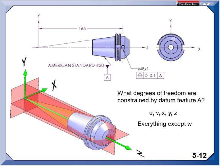
That being said, the reason why I don't think its ideal is that the set screw hole really only needs to be held in relation to the front face and central bore where the tool is inserted as 3DDave noted, so for this particular feature a customized DRF is not really necessary. In fact with most standard taper tooling the conical taper constrains all 5 DOF including translation in Z when its mounted in the spindle, so I'm not sure if custom DRF makes sense in most of those cases.
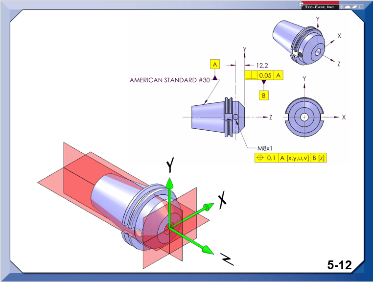
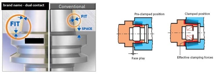
However, one could look to some of the dual contact tooling on the market for examples where a customized DRF might make sense for certain features. I believe the concept here is that the conical tapered portion engages to establish a tool axis coaxial with the spindle axis (4 DOF constrained [x,y,u,v]) - as the drawbar forces the taper together there is combined elastic deformation of the spindle/toolholder until the axial face of the holder is engaged to constrain the final DOF [z]. Now granted this may create some difficulties when taking into account the elastic deformation in inspection (restrained/clamped condition) and I'm not sure exactly how that interplays with the rules (mathematical or otherwise) of customized DRF however in order to properly account for real world assembly/interface conditions this probably needs to be accounted for anyway.
See below for some figures - I have removed the brand name but a simple google search of "dual contact toolholders" will pull up plenty of examples.