V
Villa
Guest
Hello, I am quite new with Creo (started 2 weeks ago) and I have been playing around with the Simulate option. My goal is to find how to limit the simulation, to the point I do not get an interference (body inside itself).
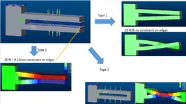
I am using a simple "U-shape" part (see image). It looks like 2 parallel beams joined on one side. Forces are applied to the middle of the beams length in opposite directions.
-Type 1 - Without a constraint, the part keeps deforming until there is a simulation error
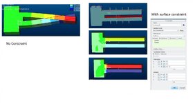
-Type 2 - I constraint (with Displacement) the edges of the part to move in Z (+/- 1.2mm). The result is way better, but the edge is moving with displacement and not with force, making the measurements a bit unclear.
This is a solution, but it is not what I am looking for. But then I change the geometry to have a "O-shaped" part. Fixed only on one side.
- Type 3 - Without a constraint the simulation runs until error.
How would it be the best option to constraint the "O-part"? Is the use of "Displacement" constraint always necessary? or is there a way to use the datum XY as a limit (that any deformation do not cross it)?
View attachment 6837
Thanks for the help!!
I am using a simple "U-shape" part (see image). It looks like 2 parallel beams joined on one side. Forces are applied to the middle of the beams length in opposite directions.
-Type 1 - Without a constraint, the part keeps deforming until there is a simulation error
-Type 2 - I constraint (with Displacement) the edges of the part to move in Z (+/- 1.2mm). The result is way better, but the edge is moving with displacement and not with force, making the measurements a bit unclear.
This is a solution, but it is not what I am looking for. But then I change the geometry to have a "O-shaped" part. Fixed only on one side.
- Type 3 - Without a constraint the simulation runs until error.
How would it be the best option to constraint the "O-part"? Is the use of "Displacement" constraint always necessary? or is there a way to use the datum XY as a limit (that any deformation do not cross it)?
View attachment 6837
Thanks for the help!!