Tek-Tips is the largest IT community on the Internet today!

Members share and learn making Tek-Tips Forums the best source of peer-reviewed technical information on the Internet!

  • Congratulations TugboatEng on being selected by the Eng-Tips community for having the most helpful posts in the forums last week. Way to Go!

Creating a construction circle with centerlines

  • Thread starter Thread starter cs05190
  • Start date Start date
C

cs05190

Guest
I've run into this problem a number of times in the past few months and was hoping to get some help with it..

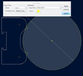
I'm drawing a part that references a ring that is not a part of the geometry. We finally found a way to get the circle to show up in the drawing.
View attachment 6553 View attachment 6554
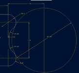
^Model Mode -- Drawing Mode^

All we did was make a sketch of the circle and change the properties within the model. Which worked and the circle is now in the part but I really would like the center lines to show up on the circle because that is how the part is dimensioned.

Like I said this is a problem I've run into a lot and I feel like there must be a simpler way to do this.

Any help with this would be great!

Thanks,
Caitie
 

Attachments

  • pic 2.JPG
    pic 2.JPG
    40.4 KB · Views: 20
  • pic 1.JPG
    pic 1.JPG
    47.6 KB · Views: 18
OK, here is the one "long" suggestion :)

from both geometry shape create parts (tube and those other shape as described),

insert general view in to ass drawing with appropriate view (front maybe) as shown in your pics,

on the Ribbon menu choose Sketch tool,

find Use edge option and than click on the both tube arc entities (that will create skecth, and you can modify those line through properties - line style),

than choose Annotate from the Ribbon menu and click Show model annotations (choose Show model datum on the sub menu and pick required axes). Important here is to have view selected before axes choosing,

now you will have axes and skecthed entities on drawing view,

on rigth drawing side see Model tree menu than click Show (next to tools pic),

choose Layer tree and you've been switched to Layer tree menu

it will appear "Active layer object selection" when you move mouse where is layer selection,

in that menu choose tube part (by click), you will see now layer tree for tube part,

pick SOLID_GEOM and right click on it and hide,

now you will have hided tube with visible axes and sketched entities as shown on your pic Drawing Mode

This is example for the Creo Parametric 2.0, and if you have some other version (WF or some else) try to find similar way to do it.

Maybe you will have some to say "config shortcomings", and you will, for example, unable to see SOLID_GEOM in layer tree.

I hope that you have already set configuration.

GL HF :)
 
Why don't you just create an datum axis in the center of your sketched circle and then show it in the drawing
 

Part and Inventory Search

Sponsor

Back
Top