Continue to Site

Eng-Tips is the largest engineering community on the Internet

Intelligent Work Forums for Engineering Professionals

  • Congratulations cowski on being selected by the Eng-Tips community for having the most helpful posts in the forums last week. Way to Go!

converting air velocity (ft/min) to CFM

Status
Not open for further replies.

PaulKraemer

Electrical
Jan 13, 2012
155
Hi,

I have some air velocity measurements (in ft/min) that were taken/measured at the center of a rectangular duct. If I want to convert these measurements to CFM, is this simply a matter of multiplying the velocity by the area of the duct? Or is there more to it than this?

Basically, I am wondering if an air velocity measurement taken at the center of a rectangular duct is representative of the air velocity in the entire duct, or if you would expect the velocity in the center of the duct to be faster (or slower) than the velocity towards the outside of the duct.

Thanks in advance,
Paul
 
Replies continue below

Recommended for you


You have to carryout velocity profile measurements to find out. The same thing when you have EPA test of stacks
 
Depends how accurate you want or need to be.

A full velocity map will help.

Or take the width of the rectangle as the diameter of a circle and use that as the area.

Remember - More details = better answers
Also: If you get a response it's polite to respond to it.
 
In answer to your specific question, the velocity at the walls goes to zero, but the boundary layer is thin, although its thickness is dependent on the velocity at the center.

TTFN (ta ta for now)
I can do absolutely anything. I'm an expert! faq731-376 forum1529 Entire Forum list
 
Hi Paul,

Please give us more information what you are trying to do, and what is application (velocities) and a problem you are trying to solve? It all depends how accurate you have to be.

Thanks,
Curtis
 
A simple search for velocity profile air duct give you some idea of what you're looking at.

Most air ducts work in laminar flow (I think) so there is a gradual change in velocity. But it also varies depending on the length of the duct where you're taking your measurments.

Right at the entrance is very different to the end of a duct 20m long.

Then you get something like this

duct_exq2vj.jpg


Remember - More details = better answers
Also: If you get a response it's polite to respond to it.
 
Hi LittleInch, Curtis2004, IRstuff, and hacksaw,

Thank you very much for your responses and I apologize for my delayed follow-up. I will do my best to describe what I am trying to do. My company builds "web" coating equipment that includes a drying tunnel. Basically, at one end of our machine we take a continuous spool of any kind of flat material (paper, foil, film, etc) and unwind it. For the purpose of this explanation, I will refer to this material as the "web". As the web is being unwound, we apply a (wet) coating to it and pass it through a drying tunnel. Here is an illustration of our drying tunnel...

HorizontalArchDryer_e3w6e7.png


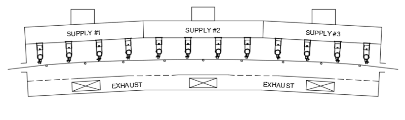
... The drying tunnel has three "Supply Zones" (labeled Supply #1, #2, and #3) into which we deliver heated air. Each Supply Zone has a dedicated / independently controlled blower and electric heater, so we can independently adjust the temperature and the flow of the air delivered into each supply zone. We do have closed-loop temperature control and closed loop control of blower RPM, but we have never tried to implement closed-loop CFM control. The air for each Supply Zone is delivered into a plenum that is isolated from the other zones at the top portion of the dryer (as indicated by the vertical lines I have drawn between the Supply Zones). The air from each Supply Plenum is directed/forced through adjustable air nozzles that aim the heated air at the web. There is no isolation between the zones in the part of the dryer that the web passes through (as this would make it impossible for the web to pass all the way through the dryer). At the bottom of the dryer, there are three 12" wide by 4" high connection points for exhaust ducts. Rather than providing separate, isolated plenums for each of the three exhaust connection points, we have a single plenum that spans the entire length of the dryer. In an effort to balance the path that the exhaust takes, we construct the top of the exhaust plenum by staggered sections of solid and perforated sheet metal (perforated indicated by dashed lines, solid indicated by solid lines). External to the dryer, three separate exhaust ducts are connected to the three 12" wide by 4" high connection points, but these ducts are then merged into a single, larger duct. This way, exhaust from the dryer can be removed by a single Exhaust Blower.

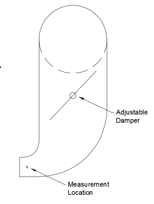
The side view of the three individual exhaust ducts looks like the following...

ExhaustDuct_ha89q3.png


The 12" wide by 4" high opening quickly transitions into an elbow that turns the duct vertical and also increases the cross-sectional area. In the vertical portion, each exhaust duct has an adjustable damper just before where it mergers into a horizontal (round) duct that goes to the single exhaust blower.

Ultimately, our goal main goal is to allow for consistent and repeatable drying of the product. While Supply Blower Speeds and temperature of the inbound air is easily controllable, measurable, and repeatable, drying conditions can be affected by the balance (or lack of balance) between the air flow that is pulled from each exhaust location. This is adjustable using the dampers, but it is not very easy to measure.

For many years, we have done this by "feel" and experience, and have almost always been able to get our customers to the point where they can repeatably achieve the degree of drying they require. More and more, I have had requests from customers to implement instrumentation for monitoring and controlling the drying conditions.

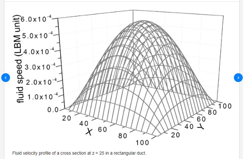
My description of the machine above is based on one we built about 20 years ago. I realize the duct-work is far from ideal for air flow measurement. For a new machine for which I knew air low measurement was desired (or required), I would advise the customer to allow/plan for longer runs of straight duct. This being said, they did manage to stick an air flow probe into the 12 x 4" Exhaust Exit locations and into the 12" x 12" Supply Zone Entry locations and they reported data measured (at the center of these locations) in ft/min. This is what led to me asking my question regarding if/how I might be able to convert this to CFM.

As to how accurate I need (or want) to be, of course I would like to be as accurate as possible, but I am sure the accuracy I can achieve will be severely limited by the fact the the existing duct work does not afford suitable measurement locations. I am interested to know based on my description of my application if any of you think this is a worthwhile exercise or if I am wasting my time.

Thanks and best regards,
Paul
 

Paul,

In a process application like that, a "go by measurement" is all you need.

So measure the flow prior to the elbow/butterfly valve, with enough distance for resonable uniform flow profile. Elbows are notorious for swirls and eddies.

A Pitot tube measurement or a single point air velocity measurement is all you need and the duct area at the point of measurement.

Of course you can profile the velocity across the duct supply to make sure for a given duct layout/blower arrangement, etc..

Once in service, the operator, in conjunction with quality control can tweak the velocity required for a given installation.

It won't be a NIST traceable measurement but it will allow you to monitor and adjust your process and production runs in a repeatable manner.

 
I have seen a number of web dryers in my career in the prepreg industry. Balancing has always been manual, and required skill and experience. Balancing was done using static pressure measurements only. The geometry of the ducting and nozzles has to be correctly designed so that given the correct static pressure, the flow through the slot nozzles will be correct and uniform. For a sheet material that blocks airflow, there were usually exhaust slots on the same side as the inlet slots so that airflow direction at the surface of the web was only in the machine direction. This was important for keeping drying conditions the same between the web center and web edges.
 
OK,

From your drawing above is the flow going left to right and then vertical?

Where is the opening on the 12" x 4" duct relative to your measuring point? A few inches to the left or some distance away?

If it's pretty close to the opening then from what I've seen the flow is actually pretty uniform across the duct. The centre might be a little faster but not as much as my previous drawing.

If these three ducts are equal then I think you can probably do it by difference between each one without having a specific air flow in mind, but if you want it then the velciaty time areas and use 90 or 95% as a decent approximation.


Remember - More details = better answers
Also: If you get a response it's polite to respond to it.
 
Status
Not open for further replies.

Part and Inventory Search

Sponsor