Greenalleycat, I see your point about the restraint. I have tried a few options:
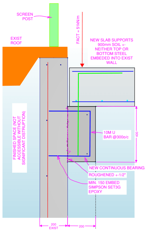
1. Fixed wall head. This would be problematic for the existing wall since it would see some moments it is not designed for. Looking at the original bldg dwgs, the existing structure does not have a slab as I suggested earlier. It is a light weight roof and the green part in the sketch is a screen post. I do not think a fixed head is applicable.
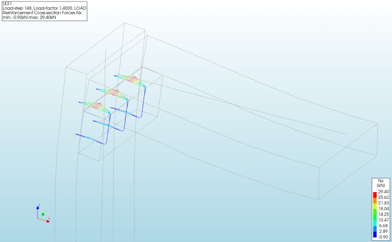
2. Pin wall head. For the forces to increase as you described I had to allow the slab to deform laterally in the XX direction. Given the slab will be supported on a new wall right of the sketch, I am not sure this would happen. Nonetheless I ran the model, and the force in the critical tie would increase from 21kN to around 29kN (sketch below). This is not feasible as you thought.
3. Wall head free/slab fixed XX at middle. This was the original model.
I chatted with the EOR, and they are amenable to the bearing detail. It turns out the new wall option was discussed at length, and the owners were adamant against it.
I thought about Dik's suggestion a little more and it made me think of another project where we were working. In that case, they installed around 900 kwik bolts and sat many long span double tees atop. I thought the idea was crazy, but I had nothing to do with it. As greenalleycat mentioned, how would the bearing ledger really differ from a technical standpoint? Where is the cutoff point for a detail like the one suggested? I do not like the epoxy solution for this, but we all live in the real world.
The fine print for the Simpson products is a bit different than Hilti's in regard to the sustained load question, so I reached out to them for their opinion.
![[pipe]](/data/assets/smilies/pipe.gif "[pipe] [pipe]")