Continue to Site

Eng-Tips is the largest engineering community on the Internet

Intelligent Work Forums for Engineering Professionals

  • Congratulations waross on being selected by the Eng-Tips community for having the most helpful posts in the forums last week. Way to Go!

Continuous Beam Questions

Status
Not open for further replies.

Steel5

Structural
Mar 25, 2017
11
What’s the most appropriate way to analyze a continuous steel wide flange beam over steel columns for flexure?

Consider a simple example:
-100 ft. long continuous steel wide flange beam (if there are any splices in the beam consider them CJP, effectively making it continuous. This may be unreasonable in practical applications, but it’s a needed simplification for me to ask my questions below)
-Beam supported on steel columns at 20 ft. O.C.
-Beam’s top flange braced by purlins every 5 ft.
-Beam’s bottom flange not braced by purlins
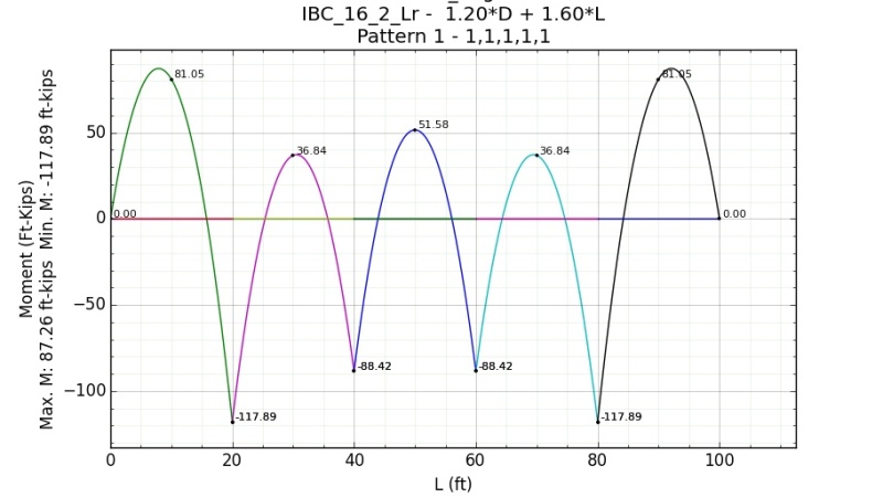
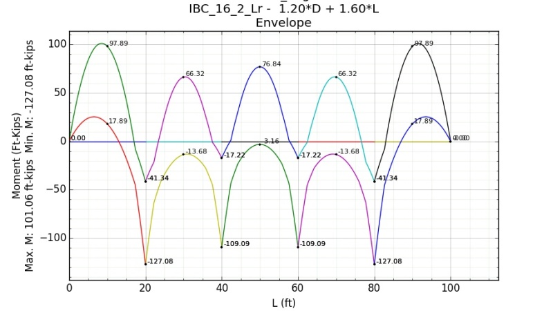
-Supports uniform gravity loads only

I’ve seen a lot of discussions on inflection points used at brace points in the past, but that AISC doesn’t allow that any more. What is the appropriate way to analyze the strength of this beam? To clarify, I’m not looking for advice on how to provide bracing to the bottom flange, I’m wondering what the proper way is to determine the strength of the beam as is.

Specifically, I have 2 questions:
1. What Cb value should be used? Do I use AISC 360-10 Equation F1-1, or some other equation? If I use F1-1, Do I use quarter points between the columns (as in, MA, MB, and MC would be 5ft. away from eachother), or something else?
2. What Lb value should be used? This seems to get overlooked in many of the discussions I’ve found on this subject. Taking Lb = 100 ft. seems way too unreasonable, the bending strength becomes so small that even a large Cb can’t make up for it. Taking Lb = 20 ft. for the column spacing might be reasonable, but I can’t find anything in the code that suggests you can do this. If you were to use the distance between inflection points for the negative moment you might get an Lb = 10ft.+/-, but this isn’t allowed by code.

To explain why Lb = 100 ft. for the full beam length is unreasonable, another way of looking at it is that if the beam were 200 ft. long (and Lb = 200 ft.) the bending strength would be even further reduced, but common sense tells us that a continuous 100 ft. beam over columns at 20 ft. O.C. should perform similarly to a 200 ft. continuous beam over columns at 20 ft. O.C.

Hopefully you understand where my confusion is coming from. Thanks for any help.
 
Replies continue below

Recommended for you

I would probably argue that Lb for negative bending should be the column to column spacing, assuming the column is braced from buckling laterally at the top.
 
1. Cb would be variable and calculated for each unbraced segment of the beam or alternatively taken as 1.
2. Lb would be the distance as defined in AISC "length between points that are either braced against lateral displacement of compression flange or braced against twist of the cross section." generally speaking in your case above for positive bending (compression in the top flange) Lb would be the 5ft purlin spacing and for negative bending (compression in the bottom flange) Lb would be your 20ft column spacing. You'll need to make sure you either have purlins at the columns or the beam to column connection and the column itself satisfy the bracing criteria of appendix 6 in the AISC specification.

To elaborate on 1 some more now that we have defined Lb, for positive bending you would calculate Cb for each 5 ft segment of beam and for negative bending for each column bay.

Patterning of roof live, snow, and rain loads will also have a large impact on the design.

Below is DL: 1 klf and LL: 1 klf on all spans with patterning considered:
1_akuxap.jpg


2_sr2i91.jpg
 
Thanks for the responses. Based on the AISC definition of Lb, how can you justify the column locations as bracing the bottom flange? I don’t see the column stopping lateral displacement of the bottom flange, nor bracing it against twist.
 
That's why I asked about bracing the column specifically. Typically in a joisted system you would provide a tie/strut joist at the column locations which would prevent the column from moving laterally. In other systems we have provided discreet bracing from the beam-column connection up into the roof framing system typically made up of angles.

Without some for of prevention for the lateral movement of the column, then LB would need to be considered the entire length of the beam.

At least that's just one guy's opinion.
 
fair point my assumption there is you either have another beam framing in or a purlin but comes down to your detailing if you have nothing else framing in at the column you can go thru the Appendix 6 analysis to see if your beam to column connection and column can satisfy the strength and stiffness requirements to consider the bottom flange braced.

Based on the envelope results to get, in my mind, an efficient beam design you'll most likely need bottom flange bracing at the columns and at the first 2 interior spans, well based solely on 1 klf once you start getting real loads those first two spans may end back up in positive bending.
 
I agree 100% with Celt83 - both on the unbraced lengths and Cb per AISC's Section F.
Also - columns would typically brace the rotation via the column-beam attachment (bolts or welds) along with vertical stiffener plates from flange to flange.


Check out Eng-Tips Forum's Policies here:
faq731-376
 
Look up CISC Cantilever (Gerber) Girders and Open Web Steel Joists. I know you are not designing a Gerber system, however, there is a good commentary on how the column/beam connections should be detailed (stiffeners, tie joists, etc..) to be considered restraint for the bottom flange at column locations.
 
Wanna try something new... Max beam length is typ 18m in these environs and qf=2.75 klf. So, if you make your splice just inside the penultimate 20' span you can use a single beam, lopped off a bit (52'). Your splice point should be about 4' past the column. Your interior span moment should be (ql^2/16) +/-68.8 k-ft and your end span moments should be(.0858ql^2) +/-94.4 k-ft. You don't have to normally consider alternate loading; it generally only affects the splice moment capacity. There's a requirment that the splice moment >= 0.25 of the section moment capacity. Your deflection would be approx 1/3 of a simple span moment deflection. Sections have to be class 1... using plastic design for analysis. Easier to design and a lot cheaper to build...

Dik
 
dik:
you describing the 5 span configuration in AISC table 3-22b in the steel manual?
 
don't know... just a quick plastic design of the 5 span 20' = 100'
2 beams 24' and 1 beam 52'... with end plate moment splices of approx 25 k-ft... and deflection of approx... 83/I (.00624ML^2/I for SS; M k-ft, L ft, I in^4). With continuity deflection is not normally an issue... loading assumed to be UDL. Done it so often, etched in grey matter...

Dik
 
ah gotcha slightly different configuration but similar concept, if I'm thinking of it correctly.
 
Canuck65... in over 45 years, I've only designed 1 Gerber system... IMHO, it's really dumb; it's not very efficient for material and a large number of pieces and multiple set-ups...

Dik
 
What if vertical stiffeners from flange to flange weren’t present, would you still consider the column-beam attachment to brace the rotation?

As a hypothetical, say the purlins from the original example are smaller wide flange beams that run over the top of the beam in question (so there’s no question those purlins only contribute to bracing the top flange). Consider the column to beam connection is a top plate with 4 bolts into the bottom flange of the beam. The column could be wide flange or HSS. Would that 4 bolt plate connection prevent the bottom flange from rotating enough to effectively brace the bottom flange for negative moment?

Would it be reasonable to say it’s braced, or would you have to prove it via appendix 6? And if you use appendix 6, would the right check be ‘6.3 Beam Bracing – 1. Lateral Bracing’, or ‘6.3 Beam Bracing – 2. Torsional Bracing’? In other words, is the column preventing lateral movement of the beam’s bottom flange, or is it preventing rotation of the beam? This calculation would involve the strength and stiffness of the column as a whole and column height would even start to play a factor in this right? If I’m way off in my thinking just let me know, I’m not as familiar with appendix 6 as I should be.

Don’t get me wrong, at no point do I think you would have to take the entire 100 ft. length as the unbraced length, I imagine that would be way too conservative, even for the hypothetical above. I think an unbraced length of 20 ft. is reasonable, I just want to have a thorough understanding of the why.

Maybe some of this comes down to the fact that a continuous beam has moment reversals (double curvature). How can you assign an unbraced length to a compression flange for a length longer than that flange is even in compression for? I know… I’m going down a dangerous path towards using inflection points… but intuitively that seems to make sense. I suppose one of the dangers in using inflection points might be that, in this example, it could lead you to use an Lb = 10ft.+/-, but when considering live load patterning you could have a compression flange than remains in compression for even longer than the column span, such as 25 ft. long which would mean you’d have to use Lb = 25 ft.+/- by the same reasoning. You’d have to constantly change your Lb for every possible load combination and patterning, which would be very difficult to design for. Maybe you guys know of some other reasons why using inflection points is bad?

Sorry for the long post, I appreciate the discussion, let me know what you think, even if it’s just a response to part of this post.
 
Steel5,

What if vertical stiffeners from flange to flange weren’t present, would you still consider the column-beam attachment to brace the rotation?
I wouldn't.
I've seen numerous structural collapses in roofs where steel wide flanges were continuous over columns without any stiffeners.
I've never seen a collapse where stiffeners were present.

How can you assign an unbraced length to a compression flange for a length longer than that flange is even in compression for?
AISC deals with this by inserting the Cb factor that takes into account the curvature (reverse or otherwise) and applying that to the full column-to-column unbraced length to get you an accurate fix on your moment capacity.

I’m going down a dangerous path towards using inflection points… but intuitively that seems to make sense.
Years ago I used to use the distance from the column to the inflection point - times 1.2 just as a feel good. I attended a seminar about that time put on by Joseph Yura of the Univ. of Texas.
A number of us asked him about this and after he thought a moment he said that he thought using that Lb (col - to - infl. point) was OK as long as you used Cb = 1.0.

One year later I was at another seminar and he had reversed his opinion and said you have to use the full distance with the proper Cb and that on no condition should you use the inflection point.

Check out Eng-Tips Forum's Policies here:
faq731-376
 
Really? I learned to design them in my first job 44 years ago. The only thing I did not know was that they were called "Gerber Beams". Never heard about Mr. Gerber until I saw the term on this website in 2007 or 2008.

No disrespect, but in MI we used it to reduce section size and facilitate the steel erection. No need for moment connections at the splices.

gjc
 
JAE, thanks for the input. When I thought of using inflection points, I was thinking of taking the distance from one inflection point to the other inflection point past the column, basically taking the entire length that the bottom flange is in compression for. That would be about twice as long as the column to inflection point, so it’d be a bit more conservative (as long as I still used Cb = 1.0). Regardless though, AISC doesn’t allow it, so I’ll steer clear of inflection points.
 
Even if not required by design, I always use stiffeners over supports... I want to maintain the cross section at the location of the first hinge... and also make sure the beam is properly braced... the unsupported length is different for plastic design. There's a 400,000 sq ft cargo terminal building near Pearson airport outside Toronto that I used plastic design for... first time engineers from NORR had ever encountered it... they were always told it was far too costly (old wives tale)... without actually doing the numbers...

Dik
 
See attached revised Moment diagram for plastic design. Envelope similar but due to distortion of end spans... only an approximate view. Also load factors slightly different.

In case anyone is curious, I copied the OP *.jpg into Paint.Net program (a very good freeware graphics program) and exported it as a *.pdf. I then used Adobe free pdf reader and added the lines... Paint.Net is a little brother to Photoshop and extremely good.

Dik
 
 http://files.engineering.com/getfile.aspx?folder=f8e86fde-995b-4b6a-81b8-c0973441b0cb&file=ContBeam.pdf
mtu1972:
The two shear-moment splices are bolted end plates and are cheap and easy to fabricate and erect... and there is a total of 3 members... Wanna bet what is cheaper... a whole bunch of Gerber connections and a whole bunch of Gerber members that have to be erected from several setups... and, compare the work for alternate loading and heavier sections to boot... a crane can easily handle the 52' member even with the 16' cantilevers hanging free in space (I'll try to dig up some photos of the long cantilevers) I'll keep doing it my way.

You'll have a tough time finding a section that is smaller...

Dik
 
Status
Not open for further replies.

Part and Inventory Search

Sponsor