Continue to Site

Eng-Tips is the largest engineering community on the Internet

Intelligent Work Forums for Engineering Professionals

  • Congratulations cowski on being selected by the Eng-Tips community for having the most helpful posts in the forums last week. Way to Go!

connection of timber beams - shear force? 6

Status
Not open for further replies.

greznik91

Structural
Feb 14, 2017
186
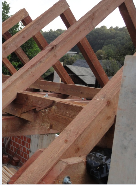
Hi, I have a question about connecting timber roof beams.

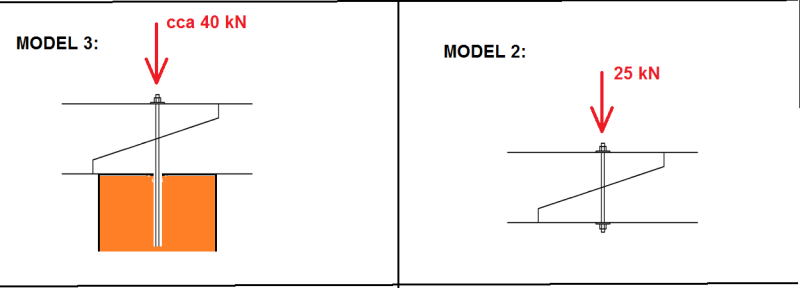
Since its pretty common, that roof beam consists from more than 1 element (span of several meters) we have to connect its elements.
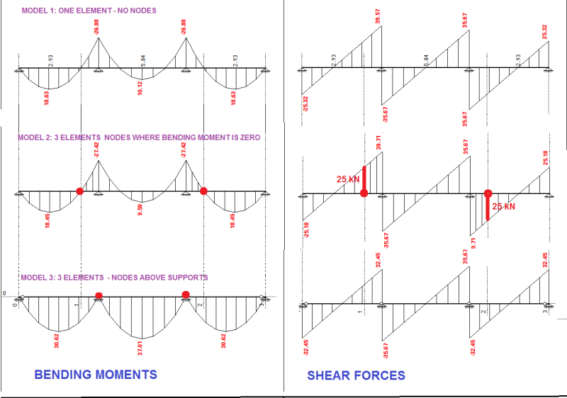
So if we have 3 elements we can connect them at/above supports (walls/columns)- MODEL 3 in picture. Other option is to make a connection at a point where bending moment diagram is zero - MODEL 2 in picture.

I found out that in MODEL 3 there are always bigger deflections which often causes problems and demands bigger beams. MODEL 2 has much lesser deflections at same load and geometry...

But what Im wondering about is what do we do about shear forces that acts AT connection (node) in MODEL 2?
How do we control it on shear force? in picture we have a shear force of 25 kN there...Element is 20/24 cm, timber C24.

I have never seen any project where engineer made a control of connection like this for a shear force. Why is that?

L1_fr3se7.png


L2_blqbh3.png
 
Replies continue below

Recommended for you

Unless you can get one piece long enough for continuous spans, we typically design wood beams as simply supported. So your model 3, but not normally connected that way.
 
Greznik91:
Take a look at a few good Wood/Timber Design textbooks or other reference materials for wood construction. What details and arrangements do you see being used out in the real world, have you ever looked, studied, thought about what you see? Which model gives you the smallest beam sizes, the lowest stresses and deflections for a given loading and span arrangement? Model 2 is a fairly common framing model because is gives shorter beam lengths, smaller beam sizes, fairly clean connection details and clean construction/erection. I’ve seen the connection detail you show, but I would not normally use it either.
 
This is typical connection in my area. You turn your connection in a way that the bolt is under tension. Turn it around and you can get splitting in both timber members. So basically you need to design the bolt and the washer so it is big enough based on compression resistance perpendicular to grain. Most of the time there are two bolts.

Edit: I'm describing model 2. I design such connections. Maybe because I am more of a wood guy. Other engineers that mostly do concrete probably don't go in so much trouble and let the carpenter do his thing.
 
Are these connections intended to be link - span connections?

I have seen them in older structures, but metal connectors are cheaper and faster.

Mike McCann, PE, SE (WA)


molibden,

With the bolts in tension due to gravity loading, the drop in span has to be lifted into place, rather than "dropping in". If I designed it and detailed it that way, I'm sure the builder would get it wrong. I understand why the wood would split, but consider this detail archaic.
 
Hokie... I did a report on a timberframed barn once and the floor timbers were 14"dp x 16"wide x 75' long... each 'stick' was at 12' o/c with floor purling between... no spices. Barn was constructed about 1850.

Dik
 
You might try "model 4" which would be similar to Model 2. To state the obvious, model two is a double cantilever with a simply supported beam on each end. You state that you've put the location of the connection "a point where bending moment diagram is zero," but in reality any location you choose for this connection will be a point of zero moment. So, you can tweak the length of the cantilevers so that the members will have manageable lengths.

I agree with msquared that a steel hanger would probably be less expensive, but if you choose to use a scarf joint, then I'd agree with hokie66 that the cantilevered end should be the lower piece. Then the reaction of the simply supported beam is transferred through bearing. Search images "timber scarf joint design" and you'll see some configurations.
 
To clarify, I did not say the cantilevered beam should be the lower piece. I was agreeing with molibden that splitting can occur with that arrangement, but the contractor wouldn't like his way.
 
hokie66, I did a lot of roofs with this detail. Some contractors just ignore it, but most of them want to do it right when I clarify the theory behind it. Erection is not so different because all of them use cranes, they crane the longer piece from side under the cantilever part and bolt it right away with crane holding it in position. Beams are light and there is no problem whatsoever.

In my area carpenters love these kind of details. They all use CNC machines to cut wood so basically it is cheaper and easier for them comparing to metal parts. Also it is nice to look at wood. I always try and conceal metal as much as possible.
 
hokie66 said:
To clarify, I did not say the cantilevered beam should be the lower piece.

Gotcha. Thanks for the clarification.
 
kipfoot said:
but if you choose to use a scarf joint, then I'd agree with hokie66 that the cantilevered end should be the lower piece. Then the reaction of the simply supported beam is transferred through bearing. Search images "timber scarf joint design" and you'll see some configurations.
Seems if the cant. end was the upper piece, it would be less likely to split as the notches would be in compression.
 
XR250 said:
Seems if the cant. end was the upper piece, it would be less likely to split...

I see your point. I'll also add that some folks have done testing to try to determine the bending capacity of a scarf joint, so not everyone is assuming it's a hinge as I suggested.
 
XR250,

Exactly the point which molibden made, and I agree.
 
XR250:
There’s nothing wrong with a little ADD(ition) here and there. Just don’t be subtractin from our effort here. :)
 
tnx for answers, but Im still confused - is a cantilevered beam lower piece or not?
 
Read again. It's all there, but you have to read to the end. If you just want to know the answer to your puzzle, you have come to the wrong place.
 
i did read it again. sorry...
Cantilever beam is upper piece.

2_m9uuc7.png


However im posting few more pictures. Some are done that way, others are not...

0_jwmscn.png


1_z8jjop.png
 
Read some Timber engineering books, some German ones have exactly this connection as an example. You can see the splitting of timber in your second picture under zero load. You can imagine what follows under extreme load. It works either way but do you want to have a weak connection in your structure? If the loads are low it doesn't really matter how you connect it...
 
Status
Not open for further replies.

Part and Inventory Search

Sponsor