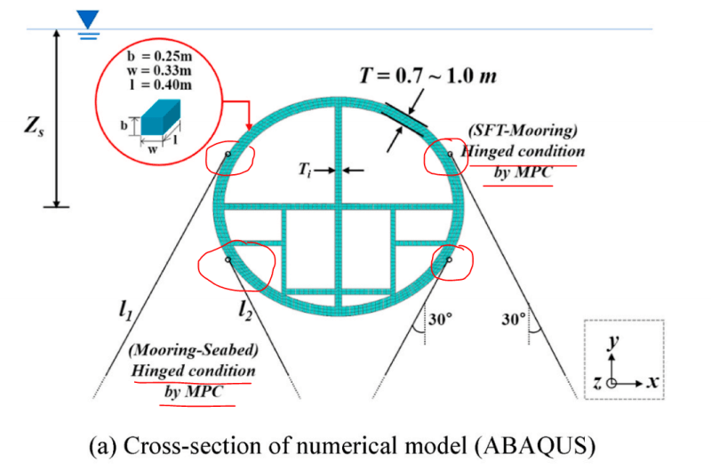
Dear experts, I would like to ask how to constrain the contact between the truss unit and the surface of the cylinder shell in ABAQUS in a reasonable way? I tried to use a mpc pin connection between the endpoints of the truss unit and a bit of the shell unit, but this results in a large stress concentration, which is not what I want. If I use the endpoints of the truss to connect to the surface of the shell at multiple points, the center of the piece will become rigid and all the stresses will be 0, which is not what I want. I would like to ask you experts if there is a good solution for this?
Tek-Tips is the largest IT community on the Internet today!
Members share and learn making Tek-Tips Forums the best source of peer-reviewed technical information on the Internet!
-
Congratulations TugboatEng on being selected by the Eng-Tips community for having the most helpful posts in the forums last week. Way to Go!
Connection of ABAQUS trusses to surfaces or sections of cylindrical shells
- Thread starter a126z
- Start date
Similar threads
- Question
- Locked
- Question
- Locked
- Question