Continue to Site

Eng-Tips is the largest engineering community on the Internet

Intelligent Work Forums for Engineering Professionals

  • Congratulations KootK on being selected by the Eng-Tips community for having the most helpful posts in the forums last week. Way to Go!

Connection eccentricity

Status
Not open for further replies.

BAGW

Structural
Jul 15, 2015
392
Hi,

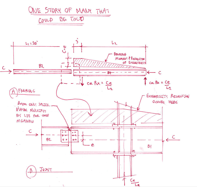
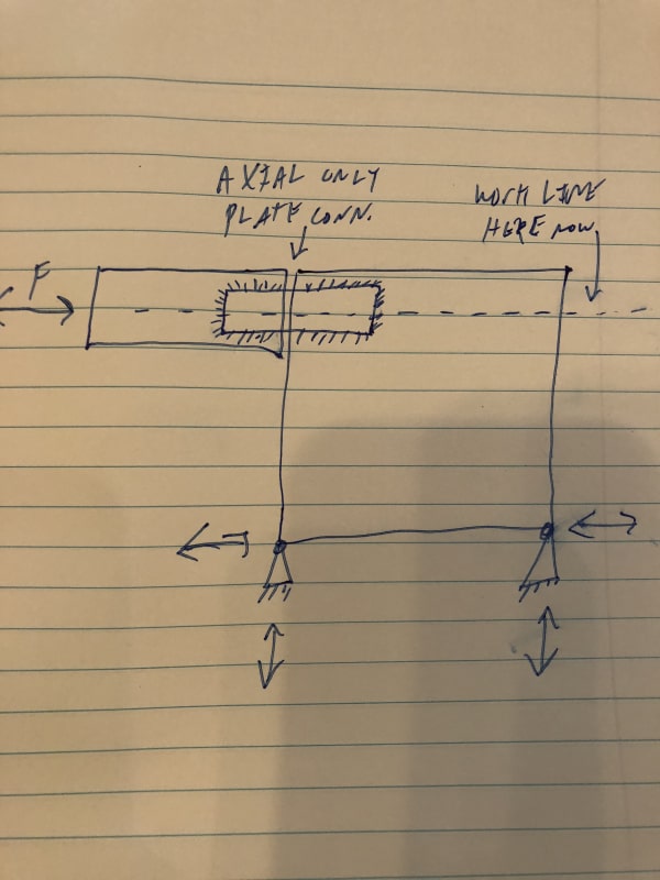
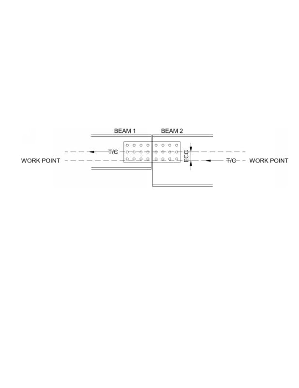
Axial force is transferred from Beam 2 to Beam 1. There is depth difference between Beam 1 and Beam 2 as shown in the image. Connection between beam 1 and beam 2 is web splice plate. There exist eccentricity between beam 1 and beam 2. Work point is at the center of depth of Beam 2. I was told that there are two ways the eccentric moment can be resisted. a) Designing the beam 2 and beam 1 for eccentric moment or b) designing the connection and beam 1 for eccentric moment. Option ‘a’ is something which I am unsure of. Can the beam be designed for eccentric moment and the connection be designed only for axial force? Is this a valid load path?

Document1_yqjrrn.jpg
 
Replies continue below

Recommended for you

That would be a different free body diagram. Even if there is a deck on the beams there has to be force resolution across the connection about the brace work line.
 
"If the plate is designed for axial compression along with the eccentric moment, is P/Pu + M/Mu < 1.0 be checked?"

No, the interaction equation proposed is not valid for this situation. Vector addition could be used to get the resultant force on individual bolts. For bearing at the bolt holes, you would need to add the horizontal force due to axial compression to the horizontal component of the force from the moment due to eccentricity, which acts about the centroid of the 12-bolt group. If P = Pu then the remaining capacity to resist the force due to moment is zero. If the axial force already equals the capacity, any moment applied will produce shear forces in the bolts that will push the total P over the capacity. Individual bolts do not have moment capacity, they only have shear capacity; furthermore, they have the same shear capacity in all directions.

I addressed strictly the theoretical aspects of using an interaction equation. In practical terms, the eccentricity is small, so the moment is small. In addition, the presumed relative stiffness of Beam 2, would reduce the moment seen by the connection even further. How much further depends on the stiffness of Beam 2 and its connection to the column, (and the stiffness of the column itself) relative to the stiffness of the connection. I proposed that since the relative stiffness is unknown and the moment is small, to greatly simplify the problem you could ignore the stiffness of Beam 2 and the direction of the vectors, and just do P * e * c / I + P / N for shear force on the bolts and bearing at the bolt holes (using the shortest edge distance). I would check compression stress at the top of the splice plates the same way except replace "N" with "A" (area of the splice plates) at the end of the equation above.
 
What are the conditions (fixity,connecting members etc) at the other ends of the beams?

Or: what assumptions were made in determining that the 'beams' have only axial forces at this point?
 
haynewp said:
That would be a different free body diagram.

Indeed it is.

C01_elybtk.png


I like to debate structural engineering theory -- a lot. If I challenge you on something, know that I'm doing so because I respect your opinion enough to either change it or adopt it.
 
I think all that could also be idealized as this. But practically I would still design the connection for the eccentricity about the work line originally shown.

84D98A86-8F47-430A-B51D-EC7779326773_gpfntz.jpg
 
Status
Not open for further replies.

Part and Inventory Search

Sponsor