Continue to Site

Eng-Tips is the largest engineering community on the Internet

Intelligent Work Forums for Engineering Professionals

  • Congratulations KootK on being selected by the Eng-Tips community for having the most helpful posts in the forums last week. Way to Go!

Connection eccentricity

Status
Not open for further replies.

BAGW

Structural
Jul 15, 2015
392
Hi,

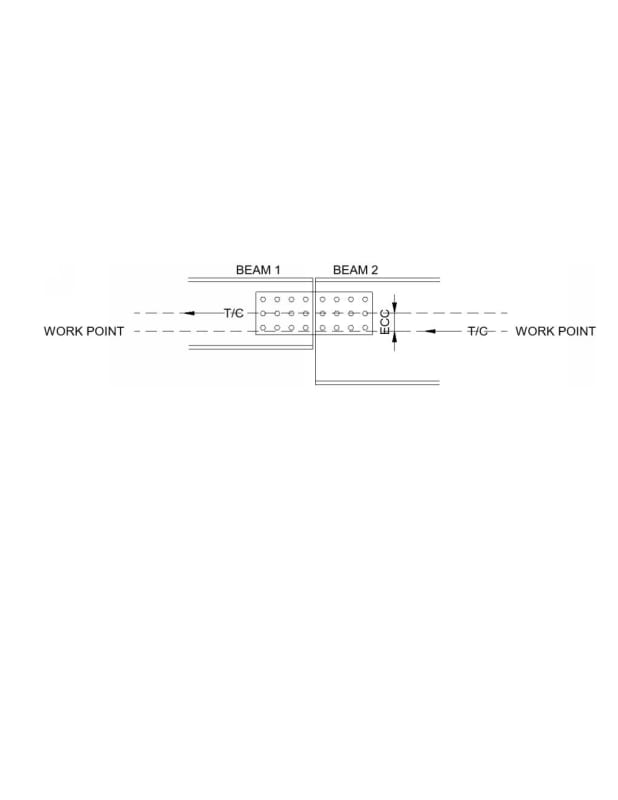
Axial force is transferred from Beam 2 to Beam 1. There is depth difference between Beam 1 and Beam 2 as shown in the image. Connection between beam 1 and beam 2 is web splice plate. There exist eccentricity between beam 1 and beam 2. Work point is at the center of depth of Beam 2. I was told that there are two ways the eccentric moment can be resisted. a) Designing the beam 2 and beam 1 for eccentric moment or b) designing the connection and beam 1 for eccentric moment. Option ‘a’ is something which I am unsure of. Can the beam be designed for eccentric moment and the connection be designed only for axial force? Is this a valid load path?
Document1_yqjrrn.jpg
 
Replies continue below

Recommended for you

Option A is valid and probably easiest for analysis. Although the easiest still is just to line up the bolt group with the centroid of the shallower beam, since the deeper beam will have eccentric loading one way or the other.
 
Why is this an issue? The axial load will go straight through, unless there is some yielding. In that case the plates would be the issue, not the larger beam.

Are these double plates? If single, then you may have an issue with transverse eccentricity.
 
Its a double plate connection. I was just wondering if plates can be sized just for axial force and the beams be designed for axial+eccentric moments. Seems like its a valid approach as pointed out by "canwesteng".
 
There are not two ways of determining moments in B1 and B2. There is only one way. The moment T.e or C.e is applied at the junction of the two beams and is distributed to each member in accordance with normal structural frame theory.

BA
 
BAretired said:
There are not two ways of determining moments in B1 and B2. There is only one way. The moment T.e or C.e is applied at the junction of the two beams
. Agreed. There is only one way of calculating ecc moment. But this moment can be resisted either by the beams B1 and B2 ( with only axial in the plates), or by beam B1 and the connection.
 
The moment at the connection will be resisted by the connection, or the connection will fail. Period. The bending and fracture capacitities of the plates, the bearing capacity at the bolt holes at the end of the webs and the ends of the splice plates, and the shear capacity of the bolts will all have to be checked for the axial load, any vertical shear, any applied moment and the moment due to eccentricity of the horizontal and vertical loads about the centroid of each side of the connection. Bolt load = M * c / I + P / N, where "c" = distance from the centroid of the 12 bolts to the furthest fasteners, "I" is the polar moment of inertia, P is the axial load, and N is the number of bolts on one side of the connection (12).
 
@HotRod10 Why cant the beam resist it?

To add to your checks, should the plates be checked for axial and bending interaction? Pu/Pc + Mu/Mc < 1.0? Axialforce is in compression always
 
This is a chord/drag strut system, right? Load coming from deck slab diaphragm? A concrete diaphragm that's probably shrinking and introducing all kinds of weird axial and flexural stresses into the supporting beams? If so, it's actually a pretty complex situation and I'm not sure that anybody could tell you exactly what happens with much accuracy. The axial load enters the beam beams at their top flanges and is only lowered by the rectifying action of the supporting columns etc. If you really want to get into the meat of this, you may need to tell us where the adjacent couple of columns are located on either side of this splice.

My thoughts based on the information available:

1) Given all of the uncertainty involved, I'd not lose a lot of sleep over allocating the moment correctly here. In fact, I'd be willing to simply design both beams and the splice for pure axial transfer only.

2) The moment coming in to the joint will get resisted by the members there in proportion to their stiffness. If one wants to get a little bit fancier than #1, I'd design the deeper beam to deal with the moment 100% and deal with no moment elsewhere.

3) Precise load distributions for stuff like this pretty unknowable. I vote for simply providing some justifiable, in the ballpark capacity for the primary structural action (axial). Chances are that your deck slab is helping out with this in ways that you haven't accounted for.

I like to debate structural engineering theory -- a lot. If I challenge you on something, know that I'm doing so because I respect your opinion enough to either change it or adopt it.
 
Hi Kootk.

This is simply a collector between braced frames. The force in this is due to compression/tension resolved components in braces. There is a concrete deck on the beam. Gravity loads are really small. The columns are located at 3' away from splice from beam 2 and 20' away from beam 1.

I like the idea of designing both beams for eccentric moment and splice for pure axial force. Do you have any concerns with this?

If there is no deck on the beam, will the load distribution change?
 
I see option B as being applicable unless the beams are connected in some additional way to share moment between the beams at the interface. Your free body needs a moment applied at the beam 1 side the way it is currently depicted.
 
BAGW said:
I like the idea of designing both beams for eccentric moment and splice for pure axial force. Do you have any concerns with this?

I'm fine with it since, as I mentioned, I'd be inclined to do nothing at all here to address the eccentricity. That said, your description of the column locations leads me to believe that beam two is going to be much stiffer than anything else coming into this joint. As such, if you insist on doing something, I feel that my proposal #2 above is substantially more rational.

BAGW said:
If there is no deck on the beam, will the load distribution change?

It will. The accounting of that will be too complex for my pea brain to comprehend however.

Beam one is going to get its rectification from the column on one end and the vertical shear in the splice connection on the other. If you're going to worry about anything fancy at the splice, I'd make it the extra vertical shear there due to this effect rather than any moment.

I like to debate structural engineering theory -- a lot. If I challenge you on something, know that I'm doing so because I respect your opinion enough to either change it or adopt it.
 
The connection must carry whatever moment is transferred through it. If the beams serve only as an axial strut, any moment due to eccentricity will be small and if the connection of Beam 2 to the column can resist moment, most of it will be resisted there and internally in Beam 2.

Without an FEA, how much of the moment is carried through the connection is unknown. Just because of that uncertainty and the small eccentricity, I would make the conservative assumption and design the connection for the moment due to eccentricity and the axial loads.

If the axial load is compression only, then yielding or buckling of the splice plates and shear on the bolts are the only possible failure modes. I would do the checks based on the superimposed stresses on the plates and the superimposed forces on the bolts. Since the actual direction of the forces due to eccentricity is difficult to predict, I would assume they act in the same direction as the axial forces and just add them together.
 
Can you use a bolted end plate? What is the size of the rolled sections and what is the magnitude of the axial load (tension/compression). I'd simply design the eccentric bolt group and pass the moments on to the respective beams.

Dik
 
If the plate is designed for axial compression along with the eccentric moment, is P/Pu + M/Mu < 1.0 be checked? Should the interaction be treated similar to beams? I could find a section in ASIC for plates interaction where above equation applies only when the plate in is tension. I dont understand why interaction need not be checked when plate in compression?
 
I'd normally check it for interaction, and, also design the connection accordingly.

Dik
 
The connection could be detailed as fixed to B2, hinged to B1. If the hinge is located at the neutral axis of B1, all of the eccentric moment goes to B2, zero moment to B1.


BA
 
BART: I'd have to think about that for a bit...

Dik
 
I had the same idea but don't know how to practically create the hinge at beam 1 except with a single bolt.
 
I'm in the KootK/Hokie camp on this one. It would not even have occurred to me to treat it as anything but an axially loaded connection.
 
Status
Not open for further replies.

Part and Inventory Search

Sponsor