I came late to the thread. I haven't studied your photos and never heard of a 3-pole anything. I just wanted to respond to your original post (even though you've got it ironed out… I found a pretty good figure showing correct configuration and composed my response, so might as well post it for posterity).
I agree with you the depictions are not always correct in this respect. It's not too surprising that depictions in textbooks are different from the physical reality. Often a 3-phase stator is depicted as 3 "coils"…. it does not come close to the physical layout. I've had more than one new EE graduate express surprise/bafflement when I tried to describe the layout of coils set into slots and wired in pole-phase groups. Bill mentioned, sometimes there is need to omit certain details to keep things manageable. And we cannot assume that everyone who writes about motor theory on the internet has studied their physical construction.
Attached is a figure from EASA dc motors document which correctly captures the position of the brushes and matches edison's description very well. It is a 4-pole motor with stator poles are located at 12:00/3:00/6:00/9:00 on the figure. They tried to depict a diamond shape rotor coil and had to pivot it out so we could see the shape of the diamond in the figure… but in reality of course the coil sides (coil legs) are positioned axially and would only appears as a point on this figure … I have drawn in circles to show where the coil sides would be.
In the top figure the coil center is at 10:30 and the associated coil sides are located half a pole pitch away at 9:00 and 12:00. Rate of change of flux thru is maximum and current is flowing. The two leads of the coil are connected to two adjacent commutator segments which are generally (*) near the center of the coil (10:30 in this case).
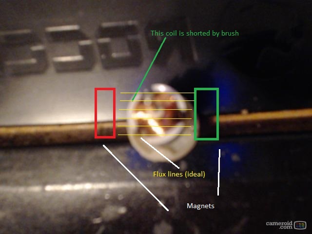
The bottom figure represents coil moved to neutral plane with coil center (and associated commutator segments) at 12:00 and the coil sides are located half a pole pitch away at 10:30 and 1:30. Rate of change of flux thru coil is minimum/zero at this location and this is approximately where commutation should occur…which is why stationary brushes would have to be positioned at approx 12:00 (and 3/6/9) so this coil will be shorted when the brush overlaps the two associated segments and then reverse when the brush ends up on the other side of these segments.
Of course as you pointed out, we don't guess about neutral position.
* There are a large variety of winding configurations possible so I'm a little cautious about generalizations.
=====================================
(2B)+(2B)' ?
")