I have a pattern of 2 holes and a rectangular cutout I want to control on a bracket (electrical connector mounting). I figure a composite tolerance is appropriate to more tightly control the pattern of the 2 holes and cutout together, compared to the part's larger datum scheme.
I understand how to apply a composite tolerance to the 2 holes' position FCF but I'm confused how to apply it to the cutout's profile FCF. What's the best way to notate that the profile should apply relative to the holes? Do I set the holes as a new datum (C) and use that datum on the cutout's profile (A|C)? Or what?
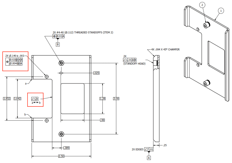
Feel free to critique other aspects of this (incomplete) drawing.")
I understand how to apply a composite tolerance to the 2 holes' position FCF but I'm confused how to apply it to the cutout's profile FCF. What's the best way to notate that the profile should apply relative to the holes? Do I set the holes as a new datum (C) and use that datum on the cutout's profile (A|C)? Or what?
Feel free to critique other aspects of this (incomplete) drawing.