Continue to Site

Eng-Tips is the largest engineering community on the Internet

Intelligent Work Forums for Engineering Professionals

  • Congratulations KootK on being selected by the Eng-Tips community for having the most helpful posts in the forums last week. Way to Go!

Complex Beam Calculation - Where to start?

Status
Not open for further replies.

MotoGoody

Structural
Nov 15, 2022
6
Hello Everyone,

I have been visiting this forum for a little while for tips but finally was stumped enough to make an account and post!

I am working on a force analysis and it is so complicated I cannot figure out where to start.

My intuition:
The most independent members to me, counterintuitively, are the small verticals. They impart a concentrated load on the horizontal "double channels", which impart a concentrated load on the vertical channels forming the frame.

Please, if anyone could point me in the right direction I would greatly appreciate it.
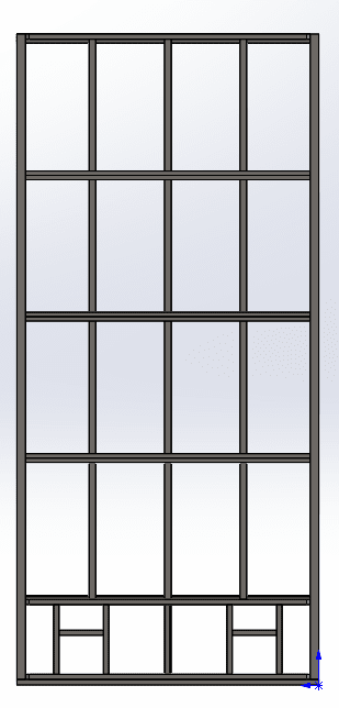
Frame_Shape_cb3q9m.png
 
Replies continue below

Recommended for you

If you assume pinned connections, you can get a fairly close approximation of the bending moments on each member by using the tributary area of each member. For instance, the side vertical will each ultimately carry the wind load from half of the door, which will be applied to the side vertical as a uniform line load along it's length.

Each of the internal verticals with glass panes can be assumed to carry the wind load on half of the glass panels on each side of it. This will be conservative, since some load will go to the horizontals above and below the panels, but to avoid the complex 2-way distribution of load, that's how I would do it.

MotoGoody said:
We ultimately hire a PE to bless the calculations but as you may have noticed, we're going through a period of loss of meaning.

The PE generally just confirms our calculations, without regard to the analysis we are trying to do. I have put in notice at this job, and I am not trying trick you all into doing my job. I simply need to learn how to do this for myself.

It's good that you're getting out of that job, since you doing the PE's job and having the PE "bless" it, is not right, nor legal. The PE is supposed to, at the very least, directly supervise the EIT doing the calculations.

However it works out with your job situation, I hope you'll not give up on engineering. It sounds like your employer has thrown you into the 'deep end of the pool' and expected you to learn to swim with no coaching. Again, this is not right, and it sounds like you've been sorely mistreated there. There are firms out there where a beginning engineer will be taught and mentored, and be able to learn and develop their skills in a healthy environment. I hope you'll seek out one of those places and continue your career in engineering.

Rod Smith, P.E., The artist formerly known as HotRod10
 
If you come back to the thread and are curious about grillage design including torsional stuff, get a copy of Blodgett's books:


I would suggest:
"Design of Welded Structures", "Design of Weldments" and "Solutions to Design of Weldments".

I don't think they'll directly help with this problem all that much, but they're all wonderful books, there's a treatment of grillages in torsion and for general stiffness that can be done by hand, which I've not seen elsewhere, and it's all immensely practical for structural and for mechanical engineers.

The last book "Solutions to Design of Weldments" isn't an answer key to the previous book, or anything like that. it's a book of worked problems by Omar Blodgett. It's hand written. He just solves a bunch of arbitrary problems. It's super interesting to walk through. It also has a more extensive table for treating welds under moment and torsion as a line. It's worth the cost just for that.

They're all likely available online now as PDFs, so you can go that route, but they're really nice to have and flip through and Lincoln sells them for less than what their printing cost would be now (if they didn't just have a giant pile of the things lying around).
 
You basically have some wind girts that transfer loads to the primary verticals. The others are largely needed only to fasten the cladding. Dumb the problem down. Could you make it more efficient, sure, but I suspect there are many mechanical aspects driving the design.

This appears to be a solidworks model in the first image. They do have a module for the analysis. It is not complicated to use for a problem like this.

I am not sure you have been reading many threads. This forum is full of analytical people and beating a problem to tears is great sport. Time to put on the big boy pants.
 
Status
Not open for further replies.

Part and Inventory Search

Sponsor