Continue to Site

Eng-Tips is the largest engineering community on the Internet

Intelligent Work Forums for Engineering Professionals

  • Congratulations KootK on being selected by the Eng-Tips community for having the most helpful posts in the forums last week. Way to Go!

Complex Beam Calculation - Where to start?

Status
Not open for further replies.

MotoGoody

Structural
Nov 15, 2022
6
Hello Everyone,

I have been visiting this forum for a little while for tips but finally was stumped enough to make an account and post!

I am working on a force analysis and it is so complicated I cannot figure out where to start.

My intuition:
The most independent members to me, counterintuitively, are the small verticals. They impart a concentrated load on the horizontal "double channels", which impart a concentrated load on the vertical channels forming the frame.

Please, if anyone could point me in the right direction I would greatly appreciate it.
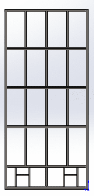
Frame_Shape_cb3q9m.png
 
Replies continue below

Recommended for you

Not sure what you got going on there, but follow load path and design members and connections for the loads.
 
Step 1. Determine how the load is distributed. 1 Way? Left/right or Up/down, 2 way?
Step 2. Find members which are loaded only by the distributed load (not loaded by others members).
Step 3. Draw a FBD for each of those members, solve reactions.
Step 4. For remaining members draw FBD with loads from distribution (as applies) and with reaction loads from members in steps 2 & 3.

based on your drawing alone, it does appear that the members that go left-right are continuous members and would take reactions from the members that go up and down. This is assuming all your connections are simple pins. If you have continuity over the members which go up and down, then you will need to consider the framing as a grillage. The loads will distribute in the grillage by relative stiffness's.


driftLimiter:

This is a door. My calculations are in regards to material choice (which size channel, s beam, etc.). The governing force is wind "into" the page. There will be glass in the "windows". It doesn't appear that any members are loaded only by the distributed load because they all interact. All joints are welded. I guess I need to look into grillage.

JStructsteel:

This thread even has it in the title, Where to start. "Follow the load path" isn't as intuitive to me as it is for you.

Edit:

I did not realize at first, but this is really unclear of how things are arranged. The vertical members are S4 beams, the perimeter is made of C7 channels, the horizontal double channels are C5 channels, and all smaller members are coped to be fit within the flanges of the channel. I see that in grillage it is generally one direction of member laid on top of the other, these are fit inside the others. Since learning the term grillage, I have not found any examples pertaining to a single planar example rather than 2 layers of beams that interface at a single plane.
 
I would check it as simple spans first, then maybe check it as a grillage. The moments from simple span will be higher in the midspan than any of the moments from the grillage case. I think many people would design the beams going left-right as continuous and up/down as simple spans.
 
This feels pretty straightforward if you make the simplifying assumption that the members are all pinned. Take the interior vertical members as spanning to the horizontal members and then design the horizontal members based on the point loads from the vertical members and you should be reasonably conservative.
 
Agreed with TLHS. I'd add that it depends on how many of these are being made. If it's just one, then assume all the members are pinned and be done with it; your analysis time will add up to more than the cost of the door with any other type of analysis.

If it's in the thousands and cost cutting/fabrication is an issue, I'd also investigate a case where all the members are continuous and what kind of connections (welded?) would be required, and what the fabrication shop is capable or willing to do, and if partial continuity is warranted (FEM is needed for that). Most of the time, easy fabrication will control the design more than getting fancy and starting to design multiple connections.
 
is this an unusually big door ?

"Hoffen wir mal, dass alles gut geht !"
General Paulus, Nov 1942, outside Stalingrad after the launch of Operation Uranus.
 
Perhaps some dimensions, loads, etc would help us get you started? Are you a engineer?
 
In my mind, assuming the door is hinged on the one side, the main challenges I see is resolving the dead loads through the framing into the hinges, and resolving the wind loads into the hinges and lock assembly.

 
This is a larger than usual door. They will roll on large wheels, supported by ASCE rail, held in the H shaped frame at the bottom. At the top of the door, it will be held in plane using another set of wheels and angles. Those angles exist in place already and we aren't responsible for their analysis- but we would be fools not to check. Believe it or not, I am capable of that calculation once I have a resultant force.

I have a BS in Mechanical Engineering but I did poorly in this subject some 8 years ago. I am not a PE. I hesitated to put any dimensions because it gets out of hand quickly. There's a difference between asking for help and someone doing the work for you, and I would really like to get some help figuring it out instead of getting the answer today and needing help forever.

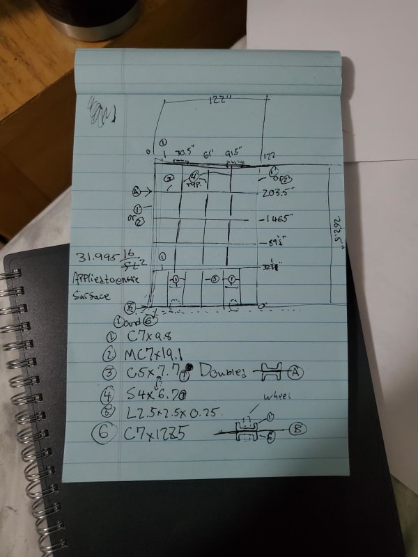
The door is 122" wide. Overall height is 262.5". Top, Sides, and bottom are C7x9.8 Channel

Vertical members are spaced 30.5" on center. (30.5", 61", 91.5"...)

Horizontal channels are doubled up at the 3 higher locations, each spaced 57" on center.

The lowest horizontal member is a single C7x9.8 channel, opening downward, spaced 32.306" from the bottom.

The bottom of the door uses a double channel because there have to be cuts made in one of them to maintain serviceability on the wheels.

Last but not least, I calculated a wind load of 31.995 psf.


so 122*263/144 = 223 sq.ft *32 = 7130 lbs !

what facing sheet are you using (to keep the door frame square, since you have no diagonal members) ?

I would divide the door into vertical strips, putting the load into the vertical C chnnls.
These are supported by the horizontal C chnnls.
These are cantilevers, so that all the load ends up on the hinge side vertical.
Then the load goes out of the door at the two hinges, something like 3600 lbs per.

clear as mud ?

"Hoffen wir mal, dass alles gut geht !"
General Paulus, Nov 1942, outside Stalingrad after the launch of Operation Uranus.
 
JStructsteel

We ultimately hire a PE to bless the calculations but as you may have noticed, we're going through a period of loss of meaning.

The PE generally just confirms our calculations, without regard to the analysis we are trying to do. I have put in notice at this job, and I am not trying trick you all into doing my job. I simply need to learn how to do this for myself.

I had a question about reducing things symmetrically. As rb1957 said, vertical strips, to the horizontals, to the verticals, etc. Since the door is symmetrical about the CL, can I treat the horizontals as cantilever beams of half their length? Also, considering that for every horizontal double channel, there is an S4 beam above and below. Don't these cancel out?

The sheeting that goes on this will make you all groan. The lower, short section will get corrugated 1/8" plate installed by others and the rest of the door will be filled with glass. We plan to use glazing tubes, probably 3x1x1/4 HSS rectangular tubing. Glass by other as well.


I think the method is from top to bottom, as ultimately the weight of the door rests on the bottom, but the main concern is the wind force. There are no hinges.

In this drawing, I included phantom wheels, rail, and top guides, as well as dimensions on the image. Top Guides and Wheels are centered at 2' 2" from the sides.

20221115_184339_snnsx0.jpg
 
"Since the door is symmetrical about the CL" ... no it isn't. it looks symmetrical, but it is supported on only one side, no? you said it's a door, presumably hinged on one side ?

"Hoffen wir mal, dass alles gut geht !"
General Paulus, Nov 1942, outside Stalingrad after the launch of Operation Uranus.
 
rb1957

Rolling door. Wheels are placed symmetrically. See the blue paper drawing I added.
 
ok, I see (none so blind ? ... as those that will not see)

so it translates, and is supported on both sides ?

one thing ... the verticals look to be "intercostals" (broken by the horizontals). This is fine, if you recognise the lack of bending continuity at these breaks ... unless you've created bending continuity over these breaks ... then that's another detail that needs to be looked at.

have you got facing sheet on both sides the C chnnls ? or only one ??

"Hoffen wir mal, dass alles gut geht !"
General Paulus, Nov 1942, outside Stalingrad after the launch of Operation Uranus.
 
You know what, let's pretend I never made this thread. I don't care and I've already given up. Too many questions about shit that doesn't matter in reference to the original thread.


I just wanted some help with beam equations. Now I'm giving up on being an engineer.
 
sorry you don't see the relavence of the questions. equations are dangerous, and we don't like handing them out (like candy to babies).

"Hoffen wir mal, dass alles gut geht !"
General Paulus, Nov 1942, outside Stalingrad after the launch of Operation Uranus.
 
Status
Not open for further replies.

Part and Inventory Search

Sponsor